by soft_techkome soft_techkome No Comments

Conveyor

Conveyor system


conveyor system is a common piece of mechanical handling equipment that moves materials from one location to another. Conveyors are especially useful in applications involving the transportation of heavy or bulky materials. Conveyor systems allow quick and efficient transportation for a wide variety of materials, which make them very popular in the material handling and packing industries. They also have popular consumer applications, as they are often found in supermarkets and airports, constituting the final leg of item/ bag delivery to customers. Many kinds of conveying systems are available and are used according to the various needs of different industries. There are chain conveyors (floor and overhead) as well. Chain conveyors consist of enclosed tracks, I-Beam, towline, power & free, and hand pushed trolleys.


Industries that use conveyor systems

A line shaft roller conveyormoves boxed produce at a distribution center

A Conveyor conveys papers at a newspaper print plant

Roller conveyor for carton transport in the apparel industry

Conveyor systems are used widespread across a range of industries due to the numerous benefits they provide.


  • Conveyors are able to safely transport materials from one level to another, which when done by human labor would be strenuous and expensive.
  • They can be installed almost anywhere, and are much safer than using a forklift or other machine to move materials.
  • They can move loads of all shapes, sizes and weights. Also, many have advanced safety features that help prevent accidents.
  • There are a variety of options available for running conveying systems, including the hydraulic , mechanical and fully automated systems, which are equipped to fit individual needs.

Conveyor systems are commonly used in many industries, including the Mining, automotive, agriculture, computer , electronic, food proccesing , aerospace , pharmaceutical, chemical, bottling and canning, print finishing and packing. Although a wide variety of materials can be conveyed, some of the most common include food items such as beans and nuts, bottles and cans, automotive components, scrap metal, pills and powders, wood and furniture and grain and animal feed. Many factors are important in the accurate selection of a conveyor system. It is important to know how the conveyor system will be used beforehand. Some individual areas that are helpful to consider are the required conveyor operations, such as transportation, accumulation and sorting, the material sizes, weights and shapes and where the loading and pickup points need to be.


Care and maintenance of conveyor systems

A conveyor system is often the lifeline to a company’s ability to effectively move its product in a timely fashion. The steps that a company can take to ensure that it performs at peak capacity, include regular inspections and system audits, close monitoring of motors and reducers, keeping key parts in stock, and proper training of personnel.

Increasing the service life of a conveyor system involves: choosing the right conveyor type, the right system design and paying attention to regular maintenance practices.

A conveyor system that is designed properly will last a long time with proper maintenance. Here are six of the biggest problems to watch for in overhead type conveyor systems including I-beam monorails, enclosed track conveyors and power and free conveyors. Overhead conveyor systems have been used in numerous applications from shop displays, assembly lines to paint finishing plants and more.

Poor take-up adjustment: this is a simple adjustment on most systems yet it is often overlooked. The chain take-up device ensures that the chain is pulled tight as it leaves the drive unit. As wear occurs and the chain lengthens, the take-up extends under the force of its springs. As they extend, the spring force becomes less and the take-up has less effect. Simply compress the take-up springs and your problem goes away. Failure to do this can result in chain surging, jamming, and extreme wear on the track and chain. Take-up adjustment is also important for any conveyor using belts as a means to power rollers, or belts themselves being the mover. With poor-take up on belt-driven rollers, the belt may twist into the drive unit and cause damage, or at the least a noticeable decrease or complete loss of performance may occur. In the case of belt conveyors, a poor take-up may cause drive unit damage or may let the belt slip off of the side of the chassis.

Lack of lubrication: chain bearings require lubrication in order to reduce friction. The chain pull that the drive experiences can double if the bearings are not lubricated. This can cause the system to overload by either its mechanical or electrical overload protection. On conveyors that go through hot ovens, lubricators can be left on constantly or set to turn on every few cycles.

Contamination: paint, powder, acid or alkaline fluids, abrasives, glass bead, steel shot, etc. can all lead to rapid deterioration of track and chain. Ask any bearing company about the leading cause of bearing failure and they will point to contamination. Once a foreign substance lands on the raceway of a bearing or on the track, pitting of the surface will occur, and once the surface is compromised, wear will accelerate. Building shrouds around your conveyors can help prevent the ingress of contaminants. Or, pressurize the contained area using a simple fan and duct arrangement. Contamination can also apply to belts (causing slippage, or in the case of some materials premature wear), and of the motors themselves. Since the motors can generate a considerable amount of heat, keeping the surface clean is an almost-free maintenance procedure that can keep heat from getting trapped by dust and grime, which may lead to motor burnout.

Product handling: in conveyor systems that may be suited for a wide variety of products, such as those in distribution centers, it is important that each new product be deemed acceptable for conveying before being run through the materials handling equipment. Boxes that are too small, too large, too heavy, too light, or too awkwardly shaped may not convey, or may cause many problems including jams, excess wear on conveying equipment, motor overloads, belt breakage, or other damage, and may also consume extra man-hours in terms of picking up cases that slipped between rollers, or damaged product that was not meant for materials handling. If a product such as this manages to make it through most of the system, the sortation system will most likely be the affected, causing jams and failing to properly place items where they are assigned. Any and all cartons handled on any conveyor should be in good shape or spills, jams, downtime, and possible accidents and injuries may result.

Drive train: notwithstanding the above, involving take-up adjustment, other parts of the drive train should be kept in proper shape. Broken O-rings on a Lineshaft, pneumatic parts in disrepair, and motor reducers should also be inspected. Loss of power to even one or a few rollers on a conveyor can mean the difference between effective and timely delivery, and repetitive nuances that can continually cost downtime.

Bad belt tracking or timing: in a system that uses precisely controlled belts, such as a sorter system, regular inspections should be made that all belts are traveling at the proper speeds at all times. While usually a computer controls this with Pulse Position Indicators, any belt not controlled must be monitored to ensure accuracy and reduce the likelihood of problems. Timing is also important for any equipment that is instructed to precisely meter out items, such as a merge where one box pulls from all lines at one time. If one were to be mistimed, product would collide and disrupt operation. Timing is also important wherever a conveyor must “keep track” of where a box is, or improper operation will result.

Since a conveyor system is a critical link in a company’s ability to move its products in a timely fashion, any disruption of its operation can be costly. Most downtime can be avoided by taking steps to ensure a system operates at peak performance, including regular inspections, close monitoring of motors and reducers, keeping key parts in stock, and proper training of personnel.


Impact and wear-resistant materials used in conveyor systems

Conveyor systems require materials suited to the displacement of heavy loads and the wear-resistance to hold-up over time without seizing due to deformation. Where static control is a factor, special materials designed to either dissipate or conduct electrical charges are used. Examples of conveyor handling materials include UHMW, nylon, Nylatron NSM, HDPE, Tivar, Tivar ESd, and polyurethane.


Growth of conveyor systems in various industries

As far as growth is concerned the material handling and conveyor system makers are getting utmost exposure in the industries like automotive, pharmaceutical, packaging and different production plants. The portable conveyors are likewise growing fast in the construction sector and by the year 2014 the purchase rate for conveyor systems in North America, Europe and Asia is likely to grow even further. The most commonly purchased types of conveyors are line-shaft roller conveyors, chain conveyors and conveyor belts at packaging factories and industrial plants where usually product finishing and monitoring are carried. Commercial and civil sectors are increasingly implementing conveyors at airports, shopping malls, etc.


Types

Belt driven roller conveyor for cartons and totes.

Flexible conveyor


  • Aero-mechanical conveyor


  • Automotive conveyor


  • Belt conveyor


  • Belt-driven live roller conveyor


  • Bucket conveyor


  • Chain conveyor


  • Chain-driven live roller conveyor


  • Drag conveyor
  • Dust-proof conveyor
  • Electric track vehicle system
  • Flexible conveyor
  • Gravity conveyor
  • Gravity skatewheel conveyor
  • Line shaft roller conveyor
  • Motorized-drive roller conveyor
  • Over head I beam conveyor
  • Overland conveyor
  • Pharmaceutical conveyor
  • Plastic belt conver
  • Pneaumatic conveyor
  • screw or auger conveyor
  • Spiral conveyor
  • Vertical conveyor
  • Vibrating conveyor
  • Wire mesh conveyor


Pneumatic

Every pneumatic system uses pipes or ducts called transportation lines that carry a mixture of materials and a stream of air. These materials are free flowing powdery materials like cement and fly ash . Products are moved through tubes by air pressure. Pneumatic conveyors are either carrier systems or dilute-phase systems; carrier systems simply push items from one entry point to one exit point, such as the money-exchanging pneaumatic tubes used at a bank drive through window. Dilute-phase systems use push-pull pressure to guide materials through various entry and exit points. Air compressors or blowers can be used to generate the air flow. Three systems used to generate high-velocity air stream:


  1. Suction or vacuum systems, utilizing a vacuum created in the pipeline to draw the material with the surrounding air. The system operated at a low pressure, which is practically 0.4–0.5 atm below atmosphere, and is utilized mainly in conveying light free flowing materials.
  2. Pressure-type systems, in which a positive pressureis used to push material from one point to the next. The system is ideal for conveying material from one loading point to a number of unloading points. It operates at a pressure of 6 atm and upwards.
  3. Combination systems, in which a suction system is used to convey material from a number of loading points and a pressure system is employed to deliver it to a number of unloading points.


Vibrating

A vibrating conveyor is a machine with a solid conveying surface which is turned up on the side to form a trough. They are used extensively in food-grade applications to convey dry bulk solids  where sanitation, washdown, and low maintenance are essential. Vibrating conveyors are also suitable for harsh, very hot, dirty, or corrosive environments. They can be used to convey newly-cast metal parts which may reach upwards of 1,500 °F (820 °C). Due to the fixed nature of the conveying pans vibrating conveyors can also perform tasks such as sorting, screening, classifying and orienting parts. Vibrating conveyors have been built to convey material at angles exceeding 45° from horizontal using special pan shapes. Flat pans will convey most materials at a 5° incline from horizontal line.


Flexible

The flexible conveyor is based on a conveyor beam in aluminium or stainless steel , with low-friction slide rails guiding a plastic multi-flexing chain. Products to be conveyed travel directly on the conveyor, or on pallets/carriers. These conveyors can be worked around obstacles and keep production lines flowing. They are made at varying levels and can work in multiple environments. They are used in food packaging, case packing, and pharmaceutical industries and also in large retail stores such asWal mart  and K mart .


Spiral

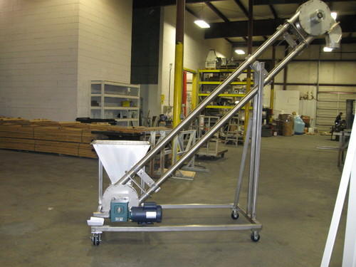
Like Vertical conveyors , spiral conveyors raise and lower materials to different levels of a facility. In contrast, spiral conveyors are able to transport material loads in a continuous flow. A helical spiral or screw rotates within a sealed tube and the speed makes the product in the conveyor rotate with the screw. The tumbling effect provides a homogeneous mix of particles in the conveyor, which is essential when feeding pre-mixed ingredients and maintaining mixing integrity. Industries that require a higher output of materials – food and beverage, retail case packaging, pharmaceuticals – typically incorporate these conveyors into their systems over standard vertical conveyors due to their ability to facilitate high throughput. Most spiral conveyors also have a lower angle of incline or decline (11 degrees or less) to prevent sliding and tumbling during operation.


Vertical

Vertical conveyors, also commonly referred to as freight lifts and material lifts, are conveyor systems used to raise or lower materials to different levels of a facility during the handling process. Examples of these conveyors applied in the industrial assembly process include transporting materials to different floors. While similar in look to freight elevators, vertical conveyors are not equipped to transport people, only materials.

Vertical lift conveyors contain two adjacent, parallel conveyors for simultaneous upward movement of adjacent surfaces of the parallel conveyors. One of the conveyors normally has spaced apart flights (pans) for transporting bulk food items. The dual conveyors rotate in opposite directions, but are operated from one gear box to ensure equal belt speed. One of the conveyors is pivotally hinged to the other conveyor for swinging the attached conveyor away from the remaining conveyor for access to the facing surfaces of the parallel conveyors.[3] Vertical lift conveyors can be manually or automatically loaded and controlled.[4] Almost all vertical conveyors can be systematically integrated with horizontal conveyors, since both of these conveyor systems work in tandem to create a cohesive material handling assembly line.

Like Spiral conveyors , vertical conveyors that use forks can transport material loads in a continuous flow. With these forks the load can be taken from one horizontal conveyor and put down on another horizontal conveyor on a different level. By adding more forks, more products can be lifted at the same time. Conventional vertical conveyors must have input and output of material loads moving in the same direction. By using forks many combinations of different input- and output- levels in different directions are possible. A vertical conveyor with forks can even be used as a vertical sorter. Compared to a spiral conveyor a vertical conveyor – with or without forks – takes up less space.

Vertical reciprocating conveyors are another type of unit handling system. Typical applications include moving unit loads between floor levels, working with multiple accumulation conveyors, and interfacing overhead conveyors line. Common material to be conveyed includes pallets, sacks, custom fixtures or product racks and more.


Heavy-duty roller

Heavy-duty roller conveyors are used for moving items that weigh at least 500 pounds (230 kg). This type of conveyor makes the handling of such heavy equipment/products easier and more time effective. Many of the heavy duty roller conveyors can move as fast as 75 feet per minute (23 m/min).

Other types of heavy-duty roller conveyors are gravity roller conveyors, chain-driven live roller conveyors, pallet accumulation conveyors, multi-strand chain conveyors, and chain and roller transfers.

Gravity roller conveyors are easy to use and are used in many different types of industries such as automotive and retail.

Chain-driven live roller conveyors are used for single or bi-directional material handling. Large, heavy loads are moved by chain driven live roller conveyors.

Pallet accumulation conveyors are powered through a mechanical clutch. This is used instead of individually powered and controlled sections of conveyors.

Multi-strand chain conveyors are used for double-pitch roller chains. Products that cannot be moved on traditional roller conveyors can be moved by a multi-strand chain conveyor.

Chain and roller conveyors are short runs of two or more strands of double-pitch chain conveyors built into a chain-driven line roller conveyor. These pop up under the load and move the load off of the conveyor.

 

by soft_techkome soft_techkome No Comments

Speeds and feeds

A line drawing showing some basic concepts of speeds and feeds in the context of lathe work. The angular velocity of the workpiece (rev/min) is called the “spindle speed” by machinists. Its tangential linear equivalent at the workpiece surface is called the “cutting speed”, “surface speed”, or simply the “speed” by machinists. The “feeds” may be for the X-axis or the Z-axis (typically mm/rev or inch/rev for lathe work; sometimes measured as mm/min or inch/min). Notice that as the tool plunges closer to the workpiece’s center, the same spindle speed will yield a decreasing surface (cutting) speed (because each rev represents a smaller circumfrance distance, but takes the same amount of time). Most cnc lathes have constant surface feed to counteract that natural decrease, which speeds up the spindle as the tool plunges in.

Milling cutter paused after taking a cut. Arrows show the vectors of various velocities collectively known as speeds and feeds. The circular arrow represents the angular velocity of the spindle (rev/min), called the “spindle speed” by machinists. The tangential arrow represents the tangential linear velocity at the outer diameter of the cutter, called the “cutting speed”, “surface speed”, or simply the “speed” by machinists. The arrow colinear with the slot that has been milled represents the linear velocity at which the cutter is advanced laterally . This velocity is called the “feed” by machinists.

The phrase speeds and feeds or feeds and speeds refers to two separate velocities in machine tool practice, cutting speed and feed rate. They are often considered as a pair because of their combined effect on the cutting process. Each, however, can also be considered and analyzed in its own right.

Cutting speed  is the speed difference between the cutting tool and the surface of the workpiece it is operating on. It is expressed in units of distance across the workpiece surface per unit of time, typically surface feey per minute  or meters  per minute   Feed rate is the relative velocity at which the cutter is advanced along the workpiece; its vector is perpendicular  to the vector of cutting speed. Feed rate units depend on the motion of the tool and workpiece; when the workpiece rotates , the units are almost always distance per spindle revolution (inches per revolution [in/rev or ipr] or millimeters per revolution . When the workpiece does not rotate , the units are typically distance per time (inches per minute or millimeters per minute , although distance per revolution or per cutter tooth are also sometimes used.

Cutting speed

Cutting speed may be defined as the rate at the workpiece surface, irrespective of the machining operation used. A cutting speed for mild steel of 100 ft/min is the same whether it is the speed of the cutter passing over the workpiece, such as in a turning operation, or the speed of the cutter moving past a workpiece, such as in a milling operation. The cutting conditions will affect the value of this surface speed for mild steel.

Schematically, speed at the workpiece surface can be thought of as the tangetial  speed at the tool-cutter interface, that is, how fast the material moves past the cutting edge of the tool, although “which surface to focus on” is a topic with several valid answers. In drilling and milling, the outside diameter of the tool is the widely agreed surface. In turning and boring, the surface can be defined on either side of the depth of cut, that is, either the starting surface or the ending surface, with neither definition being “wrong” as long as the people involved understand the difference. An experienced machinist summed this up succinctly as “the diameter I am turning from” versus “the diameter I am turning to.” He uses the “from”, not the “to”, and explains why, while acknowledging that some others do not. The logic of focusing on the largest diameter involved (OD of drill or end mill, starting diameter of turned workpiece) is that this is where the highest tangential speed is, with the most heat generation, which is the main driver of tool wear

There will be an optimum cutting speed for each material and set of machining conditions, and the spindle speed can be calculated from this speed. Factors affecting the calculation of cutting speed are:

  • The material being machined (steel, brass, tool steel, plastic, wood) (see table below)
  • The material the cutter is made from High carbon steel ,hisg speed steel, Carbide, Ceramic , and Diamond tools
  • The economical life of the cutter (the cost to regrind or purchase new, compared to the quantity of parts produced)

Cutting speeds are calculated on the assumption that optimum cutting conditions exist. These include:

  • Metal removal rate
  • Full and constant flow of cutting fluid  
  • Rigidity of the machine and tooling setup
  • Continuity of cut
  • Condition of material

The cutting speed is given as a set of constants that are available from the material manufacturer or supplier. The most common materials are available in reference books or charts, but will always be subject to adjustment depending on the cutting conditions. The following table gives the cutting speeds for a selection of common materials under one set of conditions. The conditions are a tool life of 1 hour, dry cutting (no coolant), and at medium feeds, so they may appear to be incorrect depending on circumstances. These cutting speeds may change if, for instance, adequate coolant is available or an improved grade of HSS is used (such as one that includes [cobalt]).

Spindle speed

The spindle speed is the rotational frequency of the spindle of the machine, measured in revolutions per minute (RPM). The preferred speed is determined by working backward from the desired surface speed (sfm or m/min) and incorporating the diameter (of workpiece or cutter).

Excessive spindle speed will cause premature tool wear, breakages, and can cause tool chatter, all of which can lead to potentially dangerous conditions. Using the correct spindle speed for the material and tools will greatly enhance tool life and the quality of the surface finish.

Grinding wheels are designed to be run at a maximum safe speed, the spindle speed of the grinding machine may be variable but this should only be changed with due attention to the safe working speed of the wheel. As a wheel wears it will decrease in diameter, and its effective cutting speed will be reduced. Some grinders have the provision to increase the spindle speed, which corrects for this loss of cutting ability; however, increasing the speed beyond the wheels rating will destroy the wheel and create a serious hazard to life and limb.

Spindle speed becomes important in the operation of routers, spindle moulders or shapers, and drills. Older and smaller routers often rotate at a fixed spindle speed, usually between 20,000 and 25,000 rpm. While these speeds are fine for small router bits, using larger bits, say more than 1-inch (25 mm) or 25 millimeters in diameter, can be dangerous and can lead to chatter. Larger routers now have variable speeds and larger bits require slower speed. drilling goods  generally uses higher spindle speeds than metal, and the speed is not as critical. However, larger diameter drill bits do require slower speeds to avoid burning.

Cutting feeds and speeds, and the spindle speeds that are derived from them, are the ideal cutting conditions for a tool. If the conditions are less than ideal then adjustments are made to the spindle’s speed, this adjustment is usually a reduction in RPM to the closest available speed, or one that is deemed to be correct.

Spindle speed calculations

Most metalworking books have nomograms or tables of spindle speeds and feed rates for different cutters and workpiece materials; similar tables are also likely available from the manufacturer of the cutter used.

The spindle speeds may be calculated for all machining operations once the SFM or MPM is known. In most cases, we are dealing with a cylindrical object such as a milling cutter or a workpiece turning in a lathe so we need to determine the speed at the periphery of this round object. This speed at the periphery (of a point on the circumference, moving past a stationary point) will depend on the rotational speed (RPM) and diameter of the object.

The following formulae may be used to estimate this value.

Approximation

 {\pi }

The exact RPM is not always needed, a close approximation will work (using 3 for the value of {\displaystyle {\pi }}).{\displaystyle RPM={CuttingSpeed\times 12 \over \pi \times Diameter}}

RPM = {Cutting Speed\times 12 \over \pi \times Diameter}

e.g. for a cutting speed of 100 ft/min (a plain HSS steel cutter on mild steel) and diameter of 10 inches (the cutter or the work piece){\displaystyle RPM={CuttingSpeed\times 12 \over \pi \times Diameter}={12\times 100ft/min \over 3\times 10inches}={40revs/min}}

RPM = {Cutting Speed\times 12 \over \pi \times Diameter} = {12 \times 100 ft/min \over 3 \times 10 inches} = {40 revs/min}

and, for an example using metric values, where the cutting speed is 30 m/min and a diameter of 10 mm (0.01 m),{\displaystyle RPM={Speed \over \pi \times Diameter}={1000\times 30m/min \over 3\times 10mm}={1000revs/min}}

{\displaystyle RPM={Speed \over \pi \times Diameter}={1000\times 30m/min \over 3\times 10mm}={1000revs/min}}

Accuracy

However, for more accurate calculations, and at the expense of simplicity, this formula can be used:{\displaystyle RPM={Speed \over Circumference}={Speed \over \pi \times Diameter}}

RPM = {Speed \over Circumference}={Speed \over \pi \times Diameter}

and using the same example{\displaystyle RPM={100ft/min \over \pi \times 10\,inches\left({\frac {1ft}{12\,inches}}\right)}={100 \over 2.62}=38.2revs/min}

RPM = {100 ft/min \over \pi \times 10 \, inches \left ( \frac{1 ft}{12 \, inches} \right )} = {100 \over 2.62} = 38.2 revs/min

and using the same example as above{\displaystyle RPM={30m/min \over \pi \times 10\,mm\left({\frac {1m}{1000\,mm}}\right)}={1000*30 \over \pi *10}=955revs/min}

RPM = {30 m/min \over \pi \times 10 \, mm \left ( \frac{1 m}{1000 \, mm} \right )} = {1000*30 \over \pi*10} = 955 revs/min

where:

  • RPM is the rotational speed of the cutter or workpiece.
  • Speed is the recommended cutting speed of the material in meters/minute or feet/min
  • Diameter in millimeters or inches.

Feed rate

Feed rate is the velocity at which the cutter is fed, that is, advanced against the workpiece. It is expressed in units of distance per revolution for turning and boring (typically inches per revolution [ipr] or millimeters per revolution). It can be expressed thus for milling also, but it is often expressed in units of distance per time for milling (typically inches per minute [ipm] or millimeters per minute), with considerations of how many teeth (or flutes) the cutter has then determined what that means for each tooth.

Feed rate is dependent on the:

  • Type of tool (a small drill or a large drill, high speed or carbide, a boxtool or recess, a thin form tool or wide form tool, a slide knurl or a turret straddle knurl).
  • Surface finish desired.
  • Power available at the spindle
  • Rigidity of the machine and tooling setup
  • Strength of the workpiece
  • Characteristics of the material being cut, chip flow depends on material type and feed rate. The ideal chip shape is small and breaks free early, carrying heat away from the tool and work.
  • Threads per inch  (TPI) for taps, die heads and threading tools.
  • Cut Width. Any time the width of cut is less than half the diameter, a geometric phenomenon called Chip Thinning reduces the actual chipload. Feedrates need to be increased to offset the effects of chip thinning, both for productivity and to avoid rubbing which reduces tool life.

When deciding what feed rate to use for a certain cutting operation, the calculation is fairly straightforward for single-point cutting tools, because all of the cutting work is done at one poi. With a milling machine or jointer, where multi-tipped/multi-fluted cutting tools are involved, then the desired feed rate becomes dependent on the number of teeth on the cutter, as well as the desired amount of material per tooth to cut .The greater the number of cutting edges, the higher the feed rate permissible: for a cutting edge to work efficiently it must remove sufficient material to cut rather than rub; it also must do its fair share of work.

Formula to determine feed rate

This formula can be used to figure out the feed rate that the cutter travels into or around the work. This would apply to cutters on a milling machine, drill press and a number of other machine tools. This is not to be used on the lathe for turning operations, as the feed rate on a lathe is given as feed per revolution.

FR = {RPM \times T \times CL}

{\displaystyle FR={RPM\times T\times CL}}

Where:

  • FR = the calculated feed rate in inches per minute or mm per minute.
  • RPM = is the calculated speed for the cutter.
  • T = Number of teeth on the cutter.
  • CL = The chip load or feed per tooth. This is the size of chip that each tooth of the cutter takes.

Depth of cut

Cutting speed and feed rate come together with depth of cut to determine the material removal rate , which is the volume of workpiece material (metal, wood, plastic, etc.) that can be removed per time unit.

We are dedicated, to provide, high quality products combined with excellent service. Thank you for your time and consideration. We hope you find the above in line with your requirement and eagerly look forward to serving you.

We are providing cnc repairing service  in .Amritsar,Batala, Chandigarh ,Jalandhar,Ludhiana ,Mandi Gobindgarh ,Mohali ,Patiala,Phagwara,Tarantaran ,Goraya,Hoshiarpur and in Punjab(India).

We are repairing CNC,VMC ,HMC spindle in punjab area .

Contacts; +91 7888776715,9915759967.

by soft_techkome soft_techkome No Comments

Spindle

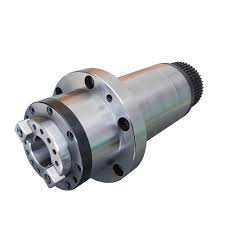
In machine tool, a spindlehttp://https://www.youtube.com/watch?v=7Qah4iledMQ is a Rotating axis of the machine, which often has a Shaft at its heart. The shaft itself is called a spindle, but also, in shop-floor practice, the word often is used metonymically to refer to the entire rotary unit, including not only the shaft itself, but its bearings and anything attached to it

A machine tool may have several , such as the headstock and tailstock on a bench lathe. That is usually the biggest one. References to “the spindle” without further qualification imply the main . Some machine tools that specialize in high-volume mass production have a group of 4, 6, or even more main .


Contents 

High speed spindle

High speed spindles are used strictly in machines, like CNC mills designed for metal work. There are two types of high speed , each with different designs:


Belt-driven spindle

Consisting of spindle and bearing shafts held within the spindle housing, the belt-driven spindle is powered by an external motor connected via a belt-pulley system.


Integral motor spindle


  • Internal Motor: limited power and torque due to restricted space within the  housing
  • Speed Range: 20,000-60,000 RPM
  • Advantage: high top speed expands application use
  • Disadvantage: sensitive life range according to use

Both types, the belt-driven and the integral motor , have advantages and disadvantages according to their design. Which one is more desirable depends on the purpose of the machine and product(s) being produced.

We are pleased to introduce ourselves, as one of the leading CNC machine repairing service provider at India, Service providing to customer for  reconditioning & repairing  in at Phagwara,Hoshiarpur ,Jalandhar,Amritsar,Batala and Ludhiana. we are also providing services at Chandigarh and near cities  Mohali , Panchkula ,Nalagarh and Baddi .We have some customer at  Ambala and surronding at  Harayana region. We are also providing cnc repairing servive at goraya near Phagwara very well.We are providing  VMC repair service in at  jalandhar and HMC  repair servive in at jalandhar. we are providing perfectcncsolution  and  top in machine tool  repair service provider in Ludhiana and  punjab.


For any machine repair related queary contact +91 7888776715,9915759967.

 Spindle

by soft_techkome soft_techkome No Comments

Milling machine


Milling is the process of machining using rotary cutters to remove material by advancing a cutter into a work piece. This may be done varying directionon one or several axes, cutter head speed, and pressure. Milling covers a wide variety of different operations and machines, on scales from small individual parts to large, heavy-duty gang milling operations. It is one of the most commonly used processes for machining custom parts to precise tolerances.

Milling can be done with a wide range of machine tools. The original class of machine tools for milling was the milling machine (often called a mill). After the advent of CNC  in the 1960s, milling machines evolved into machining centers: milling machines augmented by automatic tool changers, tool magazines , CNC capability, coolant systems, and enclosures. Milling centers are generally classified as vertical machining centers (VMC) or horizontal machining centers (HMC).


Milling Process in a milling machine

Milling is a cutting process that uses at milling cutters  to remove material from the surface of a work piece. The milling cutter is a rotary cutting tool, often with multiple cutting points. As opposed to drilling, where the tool is advanced along its rotation axis, the cutter in milling is usually moved perpendicular to its axis so that cutting occurs on the circumference of the cutter. As the milling cutter enters the work piece, the cutting edges (flutes or teeth) of the tool repeatedly cut into and exit from the material, shaving off chips from the work piece with each pass. The cutting action is shear deformation; material is pushed off the work piece in tiny clumps that hang together to a greater or lesser extent to form chips. This makes metal cutting somewhat different from slicing softer materials with a blade

The milling process removes material by performing many separate, small cuts. This is accomplished by using a cutter with many teeth, spinning the cutter at high speed, or advancing the material through the cutter slowly; most often it is some combination of these three approaches. The speeds and feeds used are varied to suit a combination of variables. The speed at which the piece advances through the cutter is called feed rate, or just feed; it is most often measured in length of material per full revolution of the cutter.

There are two major classes of milling process:


  • In face milling, the cutting action occurs primarily at the end corners of the milling cutter. Face milling is used to cut flat surfaces (faces) into the work piece, or to cut flat-bottomed cavities.
  • In peripheral milling, the cutting action occurs primarily along the circumference of the cutter, so that the cross section of the milled surface ends up receiving the shape of the cutter. In this case the blades of the cutter can be seen as scooping out material from the work piece. Peripheral milling is well suited to the cutting of deep slots, threads, and gear teeth.


Milling cutters

Many different types of cutting tools are used in the milling process. Milling cutters such as end mill may have cutting surfaces across their entire end surface, so that they can be drilled into the work piece (plunging). Milling cutters may also have extended cutting surfaces on their sides to allow for peripheral milling. Tools optimized for face milling tend to have only small cutters at their end corners.

The cutting surfaces of a milling cutter are generally made of a hard and temperature-resistant material, so that they wear  slowly. A low cost cutter may have surfaces made of high speed steel. More expensive but slower-wearing materials include cemented carbide. Thin film coatings may be applied to decrease friction or further increase hardness.

There are cutting tools typically used in milling machines or machining centers to perform milling operations . They remove material by their movement within the machine or directly from the cutter’s shape

As material passes through the cutting area of a milling machine, the blades of the cutter take swarfs of material at regular intervals. Surfaces cut by the side of the cutter therefore always contain regular ridges. The distance between ridges and the height of the ridges depend on the feed rate, number of cutting surfaces, the cutter diameter. With a narrow cutter and rapid feed rate, these revolution ridges can be significant variations in the surface finish

The face milling process can in principle produce very flat surfaces. However, in practice the result always shows visible trochodial marks following the motion of points on the cutter’s end face. These revolution marks give the characteristic finish of a face milled surface. Revolution marks can have significant roughness depending on factors such as flatness of the cutter’s end face and the degree of perpendicularity between the cutter’s rotation axis and feed direction. Often a final pass with a slow feed rate is used to improve the surface finish after the bulk of the material has been removed. In a precise face milling operation, the revolution marks will only be microscopic scratches due to imperfections in the cutting edge.

Gang milling refers to the use of two or more nilling cutters  mounted on the same arbor   in a horizontal-milling setup. All of the cutters  may perform the same type of operation, or each cutter may perform a different type of operation. For example, if several workpieces need a slot, a flat surface, and an angular groove, a good method to cut these would be gang milling. All the completed workpieces would be the same, and milling time per piece would be minimized.

Gang milling was especially important before the CNC  era, because for duplicate part production, it was a substantial efficiency improvement over manual-milling one feature at an operation, then changing machines (or changing setup of the same machine) to cut the next op. Today, CNC mills with automatic tool change and 4- or 5-axis control obviate gang-milling practice to a large extent.


Equipment

Milling is performed with a milling cutter in various forms, held in a collett or similar which, in turn, is held in the spindle of a milling machine.


Types and nomenclature

Mill orientation is the primary classification for milling machines. The two basic configuration are vertical and horizontal. However, there are alternative classifications according to method of control, size, purpose and power source.


Mill orientation


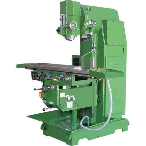
Vertical milling machine


In the vertical mill the spindle axis is vertically oriented. milling cutters  are held in the spindle and rotate on its axis. The spindle can generally be extended (or the table can be raised/lowered, giving the same effect), allowing plunge cuts and drilling. There are two subcategories of vertical mills: the bed mill and the turret mill.


  • turret mill has a stationary spindle and the table is moved both perpendicular and parallel to the spindle axis to accomplish cutting. The most common example of this type is the Bridgeport, described below. Turret mills often have a quill which allows the milling cutter to be raised and lowered in a manner similar to a drill press. This type of machine provides two methods of cutting in the vertical Zdirection: by raising or lowering the quill, and by moving the knee.
  • In the bed mill, however, the table moves only perpendicular to the spindle’s axis, while the spindle itself moves parallel to its own axis.

Turret mills are generally considered by some to be more versatile of the two designs. However, turret mills are only practical as long as the machine remains relatively small. As machine size increases, moving the knee up and down requires considerable effort and it also becomes difficult to reach the quill feed handle . Therefore, larger milling machines are usually of the bed type.

A third type also exists, a lighter machine, called a mill-drill, which is a close relative of the vertical mill and quite popular with hobbyists. A mill-drill is similar in basic configuration to a small drill press, but equipped with an X-Y table. They also typically use more powerful motors than a comparably sized drill press, with potentiometer-controlled speed and generally have more heavy-duty spindle bearings than a drill press to deal with the lateral loading on the spindle that is created by a milling operation. A mill drill also typically raises and lowers the entire head, including motor, often on a dovetailed vertical, where a drill press motor remains stationary, while the arbor raises and lowers within a driving collar. Other differences that separate a mill-drill from a drill press may be a fine tuning adjustment for the Z-axis, a more precise depth stop, the capability to lock the X, Y or Z axis, and often a system of tilting the head or the entire vertical column and powerhead assembly to allow angled cutting. Aside from size and precision, the principal difference between these hobby-type machines and larger true vertical mills is that the X-Y table is at a fixed elevation; the Z-axis is controlled in basically the same fashion as drill press, where a larger vertical or knee mill has a vertically fixed milling head, and changes the X-Y table elevation. As well, a mill-drill often uses a standard drill press-type Jacob’s chuck, rather than an internally tapered arbor that accepts collets These are frequently of lower quality than other types of machines, but still fill the hobby role well because they tend to be benchtop machines with small footprints and modest price tags.


Horizontal milling machine


The choice between vertical and horizontal spindle orientation in milling machine design usually hinges on the shape and size of a workpiece and the number of sides of the workpiece that require machining. Work in which the spindle’s axial movement is normal  to one plane, with an endmill as the cutter, lends itself to a vertical mill, where the operator can stand before the machine and have easy access to the cutting action by looking down upon it. Thus vertical mills are most favored for diesinking work (machining a mould into a block of metal).Heavier and longer workpieces lend themselves to placement on the table of a horizontal mill.


Computer numerical control

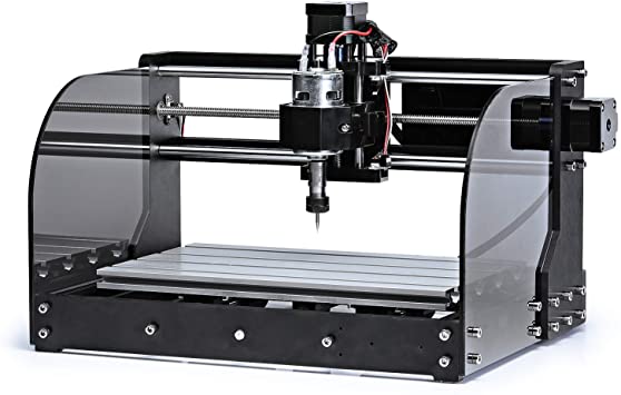
Most cnc milling machines (also called machining centers) are computer controlled vertical mills with the ability to move the spindle vertically along the Z-axis. This extra degree of freedom permits their use in diesinking, engraving applications, and 2.5D surfaces such as relief sculptures. When combined with the use of conical tools , it also significantly improves milling precision without impacting speed, providing a cost-efficient alternative to most flat-surface hand-engraving  work.


  •  

Five-axis machining center with rotating table and computer interface

CNC  machines can exist in virtually any of the forms of manual machinery, like horizontal mills. The most advanced CNC milling-machines, themulti axis , add two more axes in addition to the three normal axes Horizontal milling machines also have a C or Q axis, allowing the horizontally mounted workpiece to be rotated, essentially allowing asymmetric and eccentric center. The fifth axis  (B axis) controls the tilt of the tool itself. When all of these axes are used in conjunction with each other, extremely complicated geometries, even organic geometries such as a human head can be made with relative ease with these machines. But the skill to program such geometries is beyond that of most operators. Therefore, 5-axis milling machines are practically always programmed with cam

The operating system of such machines is a closed loop system and functions on feedback. These machines have developed from the basic NC machines. A computerized form of NC machines is known as CNC machines. A set of instructions is used to guide the machine for desired operation

We are dedicated, to provide, high quality products combined with excellent service. Thank you for your time and consideration. We hope you find the above in line with your requirement and eagerly look forward to serving you.

We are providing cnc repairing service  in .Amritsar,Batala, Chandigarh ,Jalandhar,Ludhiana ,Mandi Gobindgarh ,Mohali ,Patiala,Phagwara,Tarantaran ,Goraya,Hoshiarpur and in Punjab(India).

We are repairing CNC,VMC ,HMC spindle in punjab area .

Contacts; +91 7888776715,9915759967.

Milling machine

by soft_techkome soft_techkome No Comments

CNC Controls

Numerical control


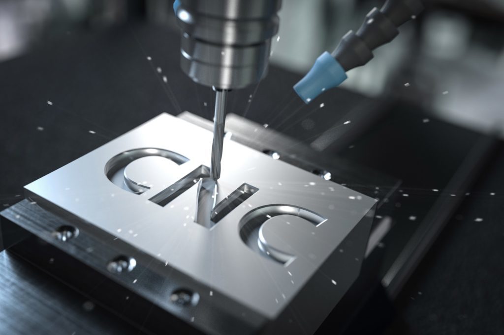
Numerical control (also computer numerical control,http://https://www.youtube.com/watch?v=mzMYlG4RQfIand commonly called CNC) is the automatic control  of Machinig  tools (drills, boring tools, lathes,Spindle ) and 3d printers  by means of a computer. A CNC machine processes a piece of material (metal, plastic, wood, ceramic, or composite) to meet specifications by following a coded programmed instruction and without a manual operator.

A CNC machine is a motorized maneuverable tool and often a motorized maneuverable platform, which are both controlled by a computer, according to specific input instructions. Instructions are delivered to a CNC machine in the form of a sequential program of machine control instructions such as G codes  and then executed. The program can be written by a person or, far more often, generated by graphical computer added design  (CAD) software. In the case of 3D printers, the part to be printed is “sliced”, before the instructions (or the program) is generated. 3D printers also use G-Code.

CNC is a vast improvement over non-computerized machining that must be manually controlled (e.g. using devices such as hand wheels or levers) or mechanically controlled by pre-fabricated pattern guides (cams ). In modern CNC systems, the design of a mechanical part and its manufacturing program is highly automated. The part’s mechanical dimensions are defined using CAD software and then translated into manufacturing directives by computer added programming (CAM) software. The resulting directives are transformed into the specific commands necessary for a particular machine to produce the component, and then are loaded into the CNC machine.

Since any particular component might require the use of a number of different tools – drills, etc. – modern machines often combine multiple tools into a single “cell”. In other installations, a number of different machines are used with an external controller and human or robotic operators that move the component from machine to machine. In either case, the series of steps needed to produce any part is highly automated and produces a part that closely matches the original CAD.


History

The first NC machines were built in the 1940s and 1950s, based on existing tools that were modified with motors that moved the tool or part to follow points fed into the system on punched tape. Those earlyservo mechanism were rapidly augmented with analog and digital computers, creating the modern CNC machine tools that have revolutionized machining processes.


Description

Motion is controlling multiple axes, normally at least two (X and Y),and a tool spindle that moves in the Z (depth). The position of the tool is driven by direct-drive stepper motors or servo motors in order to provide highly accurate movements, or in older designs, motors through a series of step-down gears. Open loop control works as long as the forces are kept small enough and speeds are not too great. On commercial metalworking machines, closed loop controls are standard and required in order to provide the accuracy, speed, and repeatbility  demanded.


Parts Description

As the controller hardware evolved, the mills themselves also evolved. One change has been to enclose the entire mechanism in a large box as a safety measure, often with additional safety interlocks to ensure the operator is far enough from the working piece for safe operation. Most new CNC systems built today are 100% electronically controlled.

CNC-like systems are used for any process that can be described as movements and operations.


Examples of CNC machines


CNC Machine Description Image
Milling machines Translates programs consisting of specific numbers and letters to move the spindle (or workpiece) to various locations and depths. Many use G code. Functions include: face milling, shoulder milling, tapping, drilling and some even offer turning. Today, CNC mills can have 3 to 6 axes. Most CNC mills require placing the workpiece on or in them and must be at least as big as the workpiece, but new 3-axis machines are being produced that are much smaller. Milling machines
Lathe Machines Cuts workpieces while they are rotated. Makes fast, precision cuts, generally using indexable tools and drills. Effective for complicated programs designed to make parts that would be infeasible to make on manual lathes. Similar control specifications to CNC mills and can often read G code. Generally have two axes (X and Z), but newer models have more axes, allowing for more advanced jobs to be machined. Lathe machines
Plasam cutter machines Involves cutting a material using a plasma torch. Commonly used to cut steel and other metals, but can be used on a variety of materials. In this process, gas (such as compressed air) is blown at high speed out of a nozzle; at the same time, an electrical arc is formed through that gas from the nozzle to the surface being cut, turning some of that gas to plasma. The plasma is sufficiently hot to melt the material being cut and moves sufficiently fast to blow molten metal away from the cut. CNC plasma cutting
Electric disharge machining (EDM), also known as spark machining, spark eroding, burning, die sinking, or wire erosion, is a manufacturing process in which a desired shape is obtained using electrical discharges (sparks). Material is removed from the workpiece by a series of rapidly recurring current discharges between two electrodes, separated by a die electic and subject to an electric voltage . One of the electrodes is called the tool electrode, or simply the “tool” or “electrode,” while the other is called the workpiece electrode, or “workpiece”. Master at top, badge die workpiece at bottom, oil jets at left (oil has been drained). Initial flat stamping will be “dapped” to give a curved surface.
Multi-spindle machines Type of screw machinesused in mass production. Considered to be highly efficient by increasing productivity through automation. Can efficiently cut materials into small pieces while simultaneously utilizing a diversified set of tooling. Multi-spindle machines have multiple spindles on a drum that rotates on a horizontal or vertical axis. The drum contains a drill head which consists of a number of spindles that are mounted on ball bearing and driven by gears.There are two types of attachments for these drill heads, fixed or adjustable, depending on whether the centre distance of the drilling spindle needs to be varied.  
Wire EDM Also known as wire cutting EDM, wire burning EDM, or traveling wire EDM, this process uses sparkerosion to machine or remove material from any electrically conductive material, using a traveling wire electrode. The wire electrode usually consists of brass- or zinc-coated brass material. Wire EDM allows for near 90-degree corners and applies very little pressure on the material. Since the wire is eroded in this process, a wire EDM machine feeds fresh wire from a spool while chopping up the used wire and leaving it in a bin for recycling.  
Sinker EDM Also called cavity type EDM or volume EDM, a sinker EDM consists of an electrode and workpiece submerged in oil or another dielectric fluid. The electrode and workpiece are connected to a suitable power supply, which generates an electrical potential between the two parts. As the electrode approaches the workpiece, dielectric breakdown occurs in the fluid forming a plasma channel and small spark jumps. Production dies and moulds are often made with sinker EDM. Some materials, such as soft ferrite materials and epoxy-rich bonded magnetic materials are not compatible with sinker EDM as they are not electrically conductive.  
Waterjet cutting Also known as a “waterjet”, is a tool capable of slicing into metal or other materials (such as granite) by using a jet of water at high velocity and pressure, or a mixture of water and an abrasive substance, such as sand. It is often used during fabrication or manufacture of parts for machinery and other devices. Waterjet is the preferred method when the materials being cut are sensitive to the high temperatures generated by other methods. It has found applications in a diverse number of industries from mining to aerospace where it is used for operations . water jetcutting machine for all materials


Tool / machine crashing

In CNC, a “crash” occurs when the machine moves in such a way that is harmful to the machine, tools, or parts being machined, sometimes resulting in bending or breakage of cutting tools, accessory clamps, vises, and fixtures, or causing damage to the machine itself by bending guide rails, breaking drive screws, or causing structural components to crack or deform under strain. A mild crash may not damage the machine or tools, but may damage the part being machined so that it must be scrapped.

Many CNC tools have no inherent sense of the absolute position of the table or tools when turned on. They must be manually “homed” or “zeroed” to have any reference to work from, and these limits are just for figuring out the location of the part to work with it, and are not really any sort of hard motion limit on the mechanism. It is often possible to drive the machine outside the physical bounds of its drive mechanism, resulting in a collision with itself or damage to the drive mechanism. Many machines implement control parameters limiting axis motion past a certain limit in addition to physical limit switches . However, these parameters can often be changed by the operator.

Many CNC tools also do not know anything about their working environment. Machines may have load sensing systems on spindle and axis drives, but some do not. They blindly follow the machining code provided and it is up to an operator to detect if a crash is either occurring or about to occur, and for the operator to manually abort the active process. Machines equipped with load sensors can stop axis or spindle movement in response to an overload condition, but this does not prevent a crash from occurring. It may only limit the damage resulting from the crash. Some crashes may not ever overload any axis or spindle drives.

If the drive system is weaker than the machine structural integrity, then the drive system simply pushes against the obstruction and the drive motors “slip in place”. The machine tool may not detect the collision or the slipping, so for example the tool should now be at 210mm on the X axis, but is, in fact, at 32mm where it hit the obstruction and kept slipping. All of the next tool motions will be off by −178mm on the X axis, and all future motions are now invalid, which may result in further collisions with clamps, vises, or the machine itself. This is common in open loop stepper systems, but is not possible in closed loop systems unless mechanical slippage between the motor and drive mechanism has occurred. Instead, in a closed loop system, the machine will continue to attempt to move against the load until either the drive motor goes into an overload condition or a servo motor fails to get to the desired position.

Collision detection and avoidance is possible, through the use of absolute position sensors (optical encoder strips or disks) to verify that motion occurred, or torque sensors or power-draw sensors on the drive system to detect abnormal strain when the machine should just be moving and not cutting, but these are not a common component of most hobby CNC tools.

Instead, most hobby CNC tools simply rely on the assumed accuracy of stepper motors  that rotate a specific number of degrees in response to magnetic field changes. It is often assumed the stepper is perfectly accurate and never missteps, so tool position monitoring simply involves counting the number of pulses sent to the stepper over time. An alternate means of stepper position monitoring is usually not available, so crash or slip detection is not possible.

Commercial CNC metalworking machines use closed loop feedback controls for axis movement. In a closed loop system, the controller monitors the actual position of each axis with an absolute or incremental encoders. With proper control programming, this will reduce the possibility of a crash, but it is still up to the operator and programmer to ensure that the machine is operated in a safe manner. However, during the 2000s and 2010s, the software for machining simulation has been maturing rapidly, and it is no longer uncommon for the entire machine tool envelope (including all axes, spindles, chucks, turrets, tool holders, tailstocks, fixtures, clamps, and stock) to be modeled accurately with 3d solid models, which allows the simulation software to predict fairly accurately whether a cycle will involve a crash. Although such simulation is not new, its accuracy and market penetration are changing considerably because of computing advancements.


Numerical precision and equipment backlash

Within the numerical systems of CNC programming it is possible for the code generator to assume that the controlled mechanism is always perfectly accurate, or that precision tolerances are identical for all cutting or movement directions. This is not always a true condition of CNC tools. CNC tools with a large amount of mechanical backlashcan still be highly precise if the drive or cutting mechanism is only driven so as to apply cutting force from one direction, and all driving systems are pressed tightly together in that one cutting direction. However a CNC device with high backlash and a dull cutting tool can lead to cutter chatter and possible workpiece gouging. Backlash also affects precision of some operations involving axis movement reversals during cutting, such as the milling of a circle, where axis motion is sinusoidal. However, this can be compensated for if the amount of backlash is precisely known by linear encoders or manual measurement.

The high backlash mechanism itself is not necessarily relied on to be repeatedly precise for the cutting process, but some other reference object or precision surface may be used to zero the mechanism, by tightly applying pressure against the reference and setting that as the zero reference for all following CNC-encoded motions. This is similar to the manual machine tool method of clamping a micrometer onto a reference beam and adjusting the Vernier dial to zero using that object as the reference.


Positioning control system

In numerical control systems, the position of the tool is defined by a set of instructions called the part programes.

Positioning control is handled by means of either an open loop or a closed loop system. In an open loop system, communication takes place in one direction only: from the controller to the motor. In a closed loop system, feedback is provided to the controller so that it can correct for errors in position, velocity, and acceleration, which can arise due to variations in load or temperature. Open loop systems are generally cheaper but less accurate. Stepper motors can be used in both types of systems, while servo motors can only be used in closed systems.

Cartesian Coordinates

The G & M code positions are all based on a three dimensional Cartesian coordinate system. This system is a typical plane often seen in mathematics when graphing. This system is required to map out the machine tool paths and any other kind of actions that need to happen in a specific coordinate. Absolute coordinates are what is generally used more commonly for machines and represent the (0,0,0) point on the plane. This point is set on the stock material in order to give a starting point or “home position” before starting the actual machining.


M-codes

[Code Miscellaneous Functions (M-Code)]. M-codes are miscellaneous machine commands that do not command axis motion. The format for an M-code is the letter M followed by two to three digits; for example:[M02 End of Program][M03 Start Spindle – Clockwise][M04 Start Spindle – Counter Clockwise][M05 Stop Spindle][M06 Tool Change][M07 Coolant on mist coolant][M08 Flood coolant on][M09 Coolant off][M10 Chuck open][M11 Chuck close][M13 BOTH M03&M08 Spindle clockwise rotation & flood coolant][M14 BOTH M04&M08 Spindle counter clockwise rotation & flood coolant][M16 Special tool call][M19 Spindle orientate][M29 DNC mode ][M30 Program reset & rewind][M38 Door open][M39 Door close][M40 Spindle gear at middle][M41 Low gear select][M42 High gear select][M53 Retract Spindle] (raises tool spindle above current position to allow operator to do whatever they would need to do)[M68 Hydraulic chuck close][M69 Hydraulic chuck open][M78 Tailstock advancing][M79 Tailstock reversing]


G-codes

G codes are used to command specific movements of the machine, such as machine moves or drilling functions. The format for a G-code is the letter G followed by two to three digits; for example G01. G-codes differ slightly between a mill and lathe application, for example:[G00 Rapid Motion Positioning][G01 Linear Interpolation Motion][G02 Circular Interpolation Motion-Clockwise][G03 Circular Interpolation Motion-Counter Clockwise][G04 Dwell (Group 00) Mill][G10 Set offsets (Group 00) Mill][G12 Circular Pocketing-Clockwise][G13 Circular Pocketing-Counter Clockwise]

We are repairing cnc machines vmc machines hmc machines in punjab india .we are providing machanical and electrical solutions we are repairng spindles ,telescopic covers , bellow covers ,appron covers and roleway covers all we are manufacring bellow covers ,telescopic covers ,role way covers.apron covers,and chip conveyores in Hoshiarpur, Punjab (Amritsar,Batala, Chandigarh ,Jalandhar ,Ludhiana ,Mandi Gobindgarh ,Mohali ,Patiala,Phagwara,Tarantaran,Goraya ,) India.

If u need any of our service kindly contact +91 7888776715,9915759967.

CNC control

by soft_techkome soft_techkome No Comments

CNC Repair

We cover all CNC systems in mainstream use in the industryhttp://https://www.youtube.com/watch?v=SZtLtfS_LCA. As always, repaired units are dynamically tested under load in real world closed loop applications.


CNC Machine Repair Services

Computer numerical control (CNC) controllers are essential for the fine and delicate work required to make the specialized parts needed for more complex machinery. If something goes wrong with one of these devices, it can spell disaster for the production process. There are numerous parts of the system of a CNC controller that could potentially develop issues, including the power controls, limit switch interfaces, servo motor drivers, protection circuitry or even the power source itself.

When it turns out that one of the more uncommon problems is what is affecting a device, it can be difficult to diagnose and even harder to conduct CNC machine repair services. Our technicians are familiar with all types of CNC controller issues whether common or unique.


Stuck Axis


One situation that can cause a CNC controller to fail is a mechanical hangup to the proper movement of one or more axis of the CNC machine itself. In order to perform all of the correct cuts, the device needs to be able to smoothly move on all three planes (x, y and z). If the CNC controller is reporting, for example, that the z-axis is stuck, this indicates that the machine is unable to properly move along that plane.

Even the slightest obstruction could be the cause of this tricky error. It may be that there is something stuck between the nut and the screw. Another possible cause of this problem is that the slides are out of alignment. Even a small issue could cause the entire cutter to freeze up, but it may be possible to narrow down the issue by running the device through the whole range of motion. Trust the our experts to identify any axis errors you’re experiencing.


Broken Emergency Stop Loop

The emergency stop loop on a CNC controller is designed to halt the operation of any machinery in case of a potential safety hazard. This is normally a good functionality to have, but occasionally the emergency stop loop will be running through the CNC system when there is no actual cause for it to be doing so, and this is known as a broken emergency stop loop.

If the controller is not enabled, and the ready light is blinking, it is possible that a broken emergency stop loop is the issue. One way to diagnose this is to disengage all emergency stop switches, and then attempt to enable the controller. It might be helpful to have one person click to enable the device while someone else watches the LED display. If the ready light blinks once after the controller is enabled, it indicates a broken emergency stop loop.

There could be numerous causes for this issue. There may be broken or detached wiring in the emergency stop box. It is also possible that there is an issue with bent or dislodged pins in the control board itself. Determining the specific cause is an involved process that requires carefully removing jumpers one at a time and turning the machine off and on again to narrow down where the problem is coming from.


Runaway Axis

When this error occurs, one axis of the machine travels too far and may even crash, which is known as “taking off.” Sometimes a damaged cable is the cause of this problem, but it may also be that the encoder needs to be replaced. One indicator of this problem is if the Positional Display numbers do not accurately reflect the change in position when the axis is moved by hand.


Complicated Issues Require Expert CNC Repair

The above issues are just a few examples of complex situations where diagnosing and repairing the cause of an error can take a lot of time, and may not have a cut and dry solution. When times like these arise, the specialized team of technicians Services is here to help solve the problem quickly and affordably. For assistance, call +91 7888776715,9915759967.

Complete the form and our representative will contact you within 1 business day.

cnc repair

by soft_techkome soft_techkome No Comments

Telescopic covers

Telescopic covers provide durable protection of slideways and precision machine components from all types of chips ,coolant and dust . Optional components can be integrated to improve durability speed, and access to the machine. Telescopic covers are used to proctect machine parts from metalic parts and dust


Today, modern machine tools process workpieces at ever-greater cutting and travel speeds. The protection of guideways, measuring systems, drive elements and other valuable parts is absolutely essential. Accelerations and speeds of machines are constantly increasing. Telescopic covers must also be able to cope with these challenges. This is where telescopic covers with harness mechanisms are used.

Manufacturer of Telescopic Covers and bellow covers , CNC Telescopic Covers and bellow covers, SS Telescopic Covers and bellow covers , Industrial Telescopic covers and bellow covers  and CNC Machines Telescopic covers and bellow covers  In Ludhiana,Jalandhar,Mohali,chanigarh,amritsar ,Batala Pathankot,Dasuya,Mukerian,Jammu,Kathua,Adampur,Mahilpur,Ropar,Moga,Firozpur,Fazilka,Muktasar,Bathinda,Sangrur,Khanna,Mandigobingarh,Ropar,Ajitgarh,SAS Nagar,SBS Nagar,Nawansahar,Tahliwal,Una, Gagret,Nakodar,Kapurthala,Phagwara,Goraya,Fillor,Focal point Ludhian,Industrial area Ludhiana,Dholewal chowk ludhiana,Chandigarh road ludhiana,Amabala road ludhiana,Kurali,Patiala,Nabha and all over Punjab and India,we are providing service in India.

Until the 1970s, telescopic covers seldom moved in speed ranges any greater than 15 m/min. The expansion and compression of the individual boxes took place sequentially. Due to the low speed, there was hardly any impact noise. Over the years, however, Improvements in drive technology have increased the travel speeds of the machines and thus also the speeds of the cover. At high travel speeds, the impact pulse exerted on the cover becomes truly enormous. This results in loud impact noises. What is more, the telescopic cover is subjected to very large mechanical stresses. The landscape for telescopic covers has changed greatly in the last few years. “Old” designs are less and less in demand, with modern concepts such as covers with differential drives taking their place.

Telescopic covers are generally produced from cold-rolled uncoated thin plates in thicknesses from 1 to 3 mm. In case of extremely aggressive environmental conditions (e.g. aggressive cooling lubricants), corrosion-resistant stainless steel plates may also be used.

At speeds below 15 m/min a telescopic cover can still be built in the conventional form of box synchronization. At higher speeds, however, the inevitable impact noises become clearly audible and unpleasant.

Telescopic covers are ideal for any machine tool application requiring complete protection of machine ways and ball screws. Telescopic way covers protect against dropped tools, heavy chip loads, cutting, oils, and coolants.


  • Can be designed to move along any machine axis.
  • We repair /replace all brands of telescopic covers.

We supply the best suitable type of Telescopic Covers for all customary machine designs, whether it is horizontal, vertical, or crossway. We are efficient to make them in different shapes such as rectangular, square etc in accordance with customers requirements. Our special designs of Telescopic Covers-Walk on Type, High Speed Covers, etc are available on special demand. They Protect Ball Screws, Guideways ,Spindles and prevent the accidental risk. These Covers undergo strict quality check, which enable them to increase the precision of your machines and their life. As we can these cover as steel cover also.if we are using steel material in telescopic covers. we can call these cover as telescopic gaurds and machine gaurds in local langauge.All cover shapes, mounting options, and wiper systems can be customized to meet your requirements. We also repair and make  all types of telescopic covers in punjab .  We are leading manufactre of bellow cover,telescopic cover,chip conveyor, appron cover,roleway cover,cnc cover, vmc cover,hmc cover in punjab india .We deals in all cities in punjab ,indiaPhagwara,Jalandhar,Kaparthula,Moga,Bathinda,Muktsar,Tarantaran,Firozpur,fazilka,sangroor,ludhiana ,Malerkotla,Mandi gobindgarh,Khanna,Fillor,Goraya, Patiala,Nabha,Mohali,Kurali,Kharar,Ropar,Nawansahar,Asron,Nangal,Tahliwal.our covers are perfect protectin for cnc machines. we Repair,Manufacctring and supply cnc covers at jalandhar as it is near to hoshiarpur.we are repairing telescopic cover in Jalandhar,Phagwara,Goraya ,Ludhiana,Mohali and Chandigarh,we also repair cnc covers(telescopic cover) in Baddi and nalagarh area.


Types of telescopic covers


Flat telescopic cover

Flat shape telesopic covers are generally used in a horizontal, lying position for milling table guides. With this design the maximum width of the telescopic cover should be limited to 1.5 m. These telescopic cover are using in VMC machine axis ,HMC machine axis ,Boring machine axis ,Milling machine axis,CNC machine axis,Zig boring machine axis,Grinding machine axis .Shape of these type of telescopic cover is flat . All sheets of this type of telescopic cover are bend at 90 degree angle. These telescopic cover are economical and frequently used


Roof shape telescopic cover

This design is always advisable when cooling lubricants are used. The inclined surface allows the water flow to the bottom side naturally also the metalic and non meatalic machined chips to run off more easily on both side of covers. With large covers (> 3 m width) for reasons of stability, etc. Two roof angles should be provided in these type of telescopic cover


Peak type Telescopic cover

These type of telescopic cover are advisable when cooling lubricants are used. The inclined surface allows the water flow to the bottom side naturally also the metalic and non meatalic machined chips to run off more easily on one side of covers. With large covers for reasons of stability, etc. Single inclined roof angles should be provided in these type of telescopic cover

These type of telescopic covers are incline to one side has a special roof shape. Depending on the possible incline, covers can be constructed with widths of up to 1.5 m. This shape is likewise a recommended solution when large amounts of coolant are present. Depending on the angle of incline, this form also helps to discharge coolants / chips.


Slant type telescopic cover

These type of telescopic covers are used in vmc machine ,hmc machine ,boring machine and cnc machines .One side of this telescopic cover is small as comapare to second side of vertical sheet.These type of telescopic cover can flow chips and coolant on both side of cover.


Flat/slope type telescopic cover

These type of telescopic cover have flattened roof shape is a special construction method with two roof angles. Primarily for dry operation and widths > 3 m. These covers are rigid in construction


Vertically Installed Telescopic Cover

Standing telescopic covers are used on larger machine tools, mostly in the area above and below the cross beam. They can take many different shapes.


Blind Telescopic Cover

With blind telescopic covers, the cover plates move in separate guide rails, each of which is mounted on the machine at the sides. It is used exclusively in a vertical arrangement. The guide rails are generally made of brass.


Cross-Beam Telescopic Cover

These telescopic covers are predominantly used on large gantry machine tools on a cross beam to the left and right of the support. The boxes are suspended vertically and protect the support guides from chips and cooling lubricants in this type of telescopic covers


DUAL-AXIS MOTION

Dual-Axis telescopic covers are typically moving behind the tables and under the spindle when space is limited. This design is limited to 3 boxes unless guide rails are used, and must be flat design for this style of telescopic cover.


WE SUPPLY TO ALL INDUSTRIES IN INDIA


Cities in Haryana

Ambala,Bahadurgarh ,Chandigarh,Faridabad ,Gurgaon,Jagadhri ,Karnal ,Panchkula Urban Estate ,Panipat ,Rewari ,Rohtak,Yamunanagar.(india)

There are ten big cities in Haryana which have Municipal Corporations, namely Gurugram, Faridabad, Rohtak, Hisar, Karnal, Panipat, Ambala, Panchkula, Yamuna Nagar and Sonepat. Eighteen smaller cities (which have Municipal Councils) namely Rewari, Narnaul, Sohna, Bhiwani, Charkhi Dadri, Palwal, Hodal, Gohana, Sirsa, Dabwali, Fatehabad, Tohana, Hansi, Jind, Narwana, Kurukshetra, Kaithal and Bahadurgarh.


Cities in Andhra Pradesh

Guntur ,Hyderabad ,Secunderabad ,Tirupati ,Vijayawada ,Visakhapatnam(india)


Cities in Bihar

Gaya ,Patna(india)


Cities in Chattisgarh

Raipur(india)


Cities in Gujarat

Ahmedabad ,Anand ,Ankaleshwar ,Bharuch ,Bhavnagar ,Gandhidham ,Gandhinagar ,Jamnagar ,Mehsana ,Morvi ,Navsari ,Porbandar ,Rajkot ,Surat ,Surendranagar ,Vadodara ,Valsad ,Vapi(india)


Cities in Himachal Pradesh

Dalhousie ,Gagret,Kangra ,Kullu ,Manali ,Parwanoo ,Shimla ,Baddi,Una Nalagarh,Hamirpur ,Tahliwal ,Pathankot,Parwanno, (india)


Cities in Jharkhand

Dhanbad ,Giridih ,Jamshedpur ,Ranchi(india)


Cities in Karnataka

Bangalore ,Belgaum ,Coorg ,Hubli ,Mangalore ,Mysore ,Udupi(india)


Cities in Kerala

Alappuzha ,Guruvayur ,Idukki ,Kannur ,Kochi ,Kollam ,Kottayam ,Kovalam ,Kozhikode ,Munnar ,Palakkad ,Thekkady ,Thiruvananthapuram ,Trichur(india)


Cities in Madhya Pradesh

Bhopal ,Gwalior ,Indore ,Jabalpur ,Kanha ,Khajuraho ,Ujjain(india)


Cities in Maharashtra

Aurangabad ,Jalgaon ,Kalyan ,Khandala ,Kolhapur ,Mahabaleshwar ,Matheran ,Mumbai ,Nagpur ,Navi Mumbai ,Panchgani ,Pune ,Raigad ,Sangli ,Satara ,Shirdi ,Thane ,Ulhasnagar ,Vasai(india)


Cities in Orissa

Bhubaneshwar ,Cuttack ,Puri (india)


Cities in Pondicherry

Auroville ,Karaikal(india)


Cities in Punjab

Amritsar,Batala, Chandigarh ,Jalandhar ,Ludhiana ,Mandi Gobindgarh ,Mohali ,Patiala,Phagwara,Tarantaran,SAS Nagar,SBS Nagar,Bathinda ,Moga,Pathankot ,Abohar,Maler kotla,Khanna,Phagwara,Muktsar,Barnala Firozpur,Kaphurthala,Zirakpur,Rajpura ,Gurdaspur,,Kotkapura,Sangroor,Faridkot,Mansa,Hoshiarpur, Jammu . (india)


Cities in Rajasthan

Ajmer ,Alwar ,Bhilwara ,Bhiwadi ,Bikaner ,Jaipur ,Jaisalmer ,Jodhpur ,Kota ,Mount Abu ,Pushkar ,Sawai Madhopur ,Udaipur(india)


Cities in Tamil Nadu

Chennai ,Coimbatore ,Erode ,Hosur ,Kanchipuram ,Kanyakumari ,Karur ,Kodaikanal ,Madurai ,Nagercoil ,Namakkal ,Nilgiris ,Salem ,Sivakasi ,Thanjavur ,Tirunelveli ,Tiruppur ,Trichy ,Tuticorin ,Udagamandalam ,Vellore(india)


Cities in Uttar Pradesh

Agra ,Aligarh ,Allahabad ,Bareilly ,Bhadohi ,Ghaziabad ,Greater Noida ,Kanpur ,Lucknow ,Mathura ,Meerut ,Moradabad ,Noida ,Saharanpur ,Sahibabad ,Varanasi(india)


Cities in Uttaranchal

Dehradun ,Garhwal ,Haridwar ,Mussoorie ,Nainital ,Rishikesh ,Roorkee ,Rudraour(india)


Cities in West Bengal

Asansol ,Darjeeling ,Durgapur ,Howrah ,Kalimpong ,Kolkata ,Siliguri(india)

There are many companies throughout the world who manufacture or sell Telescopic Steel Covers. Our company has achieved production levels – in terms of volume and quality standards – that place it at the top of the market. Heavy investment in machinery and personnel training, under the guidance of highly qualified engineers have allowed us to face the latest challenge in the development of Machine Tools: the use of high speed linear motors and the increase of the axis speeds. The quality of design and manufacture, often with patented shock absorbers, allow us to solve problems resulting from high speeds. At the same time, our company gives utmost consideration to the quality/price ratio, insuring that our customers get the most from their investment.


kindly contect +917888776715, 9915759967

Telescopic cover


 https://en.wikipedia.org/wiki/Telescoping_(mechanics)