by soft_techkome soft_techkome No Comments

Machine Covers ,CNC Covers.

Machine covers

In case you do not know, elements like dust, dirt, oil, and water cause disaster and harmful to plants production and machines . The damage it causes is severe and leads to expensive repairs of machines and its parts. These element damages can be averted with the use of our machine covers  and tarps can provide the proper and perfect protection for machinery. With our industrial machine covers it is beneficial and would prevent most of these elements from damaging machinery.


Benefits 


  • Preventing machinery damage
  • Containing hazardous oil, dirt & dust
  • Preventing accidents
  • Improving facility cleanliness
  • Protecting against the sun, grime, grease, and oil


Professional Clean Apperance


Weighty Duty Protective Covers for Machines

In the production of custom covers our priority is to shield machines from elements of damage and the materials we use are also ideal for welding facilities where sparks are in close proximity to valuable equipment. These material is flame retardant and is resistant to tearing.


Usages

Our machine covers give you guarantee of keeping any type of industrial machine protected. With covers protection of machinery in storage warehouses, manufacturing plants, auto body shops, packaging plants and many other locations where heavy-duty protective covers from damaging elements you are assured of your machines safety.

If you have any inquiries about machines , hydraulic cylinder u can contact us at any time in a week we are repairing cnc machines,Telescopic covers Repair ,Bellow covers Repair ,Apron cover Repair .Roll way cover Repair ,Hydraulic cylinders Repair ,Mechanical parts repair,  Spindle Repair , Ball screw Repair,Guide way Repair ,Lubrication Pump Repair ,Hydraulic cylinder Repair, CNC Machine Repair service ,VMC Machine Repair service,Preventive Maintenance service,HMC Machine repair service,Index table repair service,Rotary table repair service,Coolant pump repair service ,Counter balancing cylinder repair service,Panel ac repair service in Hoshiarpur,Jalandhar,Phagwara,Goraya,Ludhiana,Amritsar,Tarantaran,Patti,Batala,Gurdaspur,Pathankot,Jammu,Mukerian,Dasuya,Tanda,Gagret,Una,Baddi,Nangal,Tahliwal,Garhshankar,Anandpur sahib,Ropar,Nawansahar,Mandi gobindgarh, khanna,Moahli,Chandigarh,Nalagarh,Nasrala,Samarala,Rajpura,Patiala,Nabha,Malerkotla ,Bathinda,Moga,Firozpur and in all punjab and india.

Contact +91 7888776715,9915759967.


https://techkome.com/telescopic-covers/

by soft_techkome soft_techkome No Comments

Air compressor

An air compressor is a device that converts power  (using an electric motor, diesel or gasoline engine, etc.) into potential energy stored in pressurized air (i.e., compressed air ). By one of several methods, an air compressor forces more and more air into a storage tank, increasing the pressure. When the tank’s pressure reaches its engineered upper limit, the air compressor shuts off. The compressed air, then, is held in the tank until called into use.The energy contained in the compressed air can be used for a variety of applications, utilizing the kinetic energy of the air as it is released and the tank depressurizes. When tank pressure reaches its lower limit, the air compressor turns on again and re-pressurizes the tank. An air compressor must be differentiated from a pump because it works for any gas/air, while pumps work on a liquid.


Contents


Classification

Compressors can be classified according to the pressure delivered:


  1. Low-pressure air compressors (LPACs), which have a discharge pressure of 150 psi or less
  2. Medium-pressure compressors which have a discharge pressure of 151 psi to 1,000 psi
  3. High-pressure air compressors (HPACs), which have a discharge pressure above 1,000 psi

They can also be classified according to the design and principle of operation:


  1. Single-stage reciprocatin compressor
  2. Two-stage reciprocating compressor
  3. Compound compressor
  4. Rotary air compressorr
  5. Rotary vane pump
  6. Scroll compressor
  7. Turbo compressor
  8. Centrifugal compressorn


Displacement type

There are numerous methods of air compression, divided into either positive-displacement or roto-dynamic types.


Positive displacement

Positive-displacement compressors work by forcing air in a chamber whose volume is decreased to compress the air. Once the maximum pressure is reached, a port or valve opens and air is discharged into the outlet system from the compression chamber.Common types of positive displacement compressors are


  • Piston-type: air compressors use this principle by pumping air into an air chamber through the use of the constant motion of pistons. They use one-way valves to guide air into and out of a chamber whose base consists of a moving piston. When the piston is on its down stroke, it draws air into the chamber. When it is on Technical Illustration of a two-stage air compressorits up stroke, the charge of air is forced out and into a storage tank. Piston compressors generally fall into two basic categories, single-stage and two-stage. Single stage compressors usually fall into the fractional through 5 horse power range. Two-stage compressors normally fall Technical Illustration of a portable single-stage air compressorinto the 5 through 30 horsepower range. Two-stage compressors provide greater efficiency than their single-stage counterparts. For this reason, these compressors are the most common units within the small business community. The capacities for both single-stage and two-stage compressors is generally provided in horsepower (HP), Standard cubic feet per minute  (SCFM)* and pounds per square inch  (PSI). *To a lesser extent, some compressors are rated in Actual cubic feet per minute (ACFM). Still others are rated in cubic feet per minute (CFM). Using CFM to rate a compressor is incorrect because it represents a flow rate that is independent of a pressure reference. i.e. 20 CFM at 60 PSI.
  • Rotary air compressor : use positive-displacement compression by matching two helical screws that, when turned, guide air into a chamber, whose volume is decreased as the screws turn.
  • Vane compressors: use a slotted rotor with varied blade placement to guide air into a chamber and compress the volume. This type of compressor delivers a fixed volume of air at high pressures.


Dynamic displacement

Dynamic displacement air compressors include cenrifugal compressor  and axial compressors. In these types, a rotating component imparts its kinetic energy to the air which is eventually converted into pressure energy. These use centrifugal force generated by a spinning impeller to accelerate and then decelerate captured air, which pressurizes it.


Cooling

Due to adibatic heating , air compressors require some method of disposing of waste heat . Generally this is some form of air- or water-cooling, although some (particularly rotary type) compressors may be cooled by oil (that is then in turn air- or water-cooled). The atmospheric changes are also considered during cooling of compressors. The type of cooling is determined by considering the factors such as inlet temperature, ambient temperature, power of the compressor and area of application. There is no single type of compressor that could be used for any application.


Applications

Air compressors have many uses, including: supplying high-pressure clean air to fill gas cylinders , supplying moderate-pressure clean air to a submerged surface supplied diver , supplying moderate-pressure clean air for driving some office and school building   pneaumatic HVAC control systems valves, supplying a large amount of moderate-pressure air to power pneaumatic tools , such as jack hammers , filling high pressure air tanks (HPA), for filling tires and to produce large volumes of moderate-pressure air for large-scale industrial processes (such as oxidation for petroleum coking or cement plant bag house purge systems).

Most air compressors either are reciprocating piston type, rotary vane or rotary pump . Centrifugal compressors are common in very large applications, while rotary screw, scroll,and reciprocating air compressors are favored for smaller, portable applications.

There are two main types of air-compressor pumps: oil-injected and oil-less. The oil-less system has more technical development, but is more expensive, louder and lasts for less time than oil-lubed pumps. The oil-less system also delivers air of better quality.

Air compressors are designed to utilize a variety of power sources. While gas/diesel-powered and electric air compressors are among the most popular, air compressors that utilize vehicle engines, power take off , or hydraulic ports are also commonly used in mobile applications.

The power of a compressor is measured in HP (horse power ) and CFM (ccubic feet per minute  of intake air).The gallon size of the tank specifies the volume of compressed air (in reserve) available. Gas/diesel powered compressors are widely used in remote areas with problematic access to electricity. They are noisy and require ventilation for exhaust gases. Electric powered compressors are widely used in production, workshops and garages with permanent access to electricity. Common workshop/garage compressors are 110-120 Volt or 230-240 Volt. Compressor tank shapes are: “pancake”, “twin tank”, “horizontal”, and “vertical”. Depending on a size and purpose compressors can be stationary or portable.


Maintenance

To ensure all compressor types run efficiently with no leaks, it is imperative to perform routine maintenance, such as monitoring and replacing air compressor fittings. It is suggested that air compressor owners perform daily inspections of their equipment, such as:


  • Checking for oil and air leaks
  • Checking the differential pressure in the compressed air filter
  • Determining whether or not the oil in the compressor should be changed
  • Verifying safe operating temperature
  • Draining condensation from air receiver tanks

If you have any inquiry about Air compressor repair,hand wheel repair in Punjab and India u can contact us at any time in a week we are repairing cnc machines,Telescopic covers Repair ,Bellow covers Repair ,Apron cover Repair .Roll way cover Repair ,Hydraulic cylinders Repair ,Mechanical parts repair, Machine Spindle Repair , Ball screw Repair,Guide way Repair ,Lubrication Pump Repair ,Hydraulic cylinder Repair, CNC Machine Repair service ,VMC Machine Repair service,Preventive Maintenance service,HMC Machine repair service,Index table repair service,Rotary table repair service,Coolant pump repair service ,Counter balancing cylinder repair service,Panel ac repair service in Hoshiarpur,Jalandhar,Phagwara,Goraya,Ludhiana,Amritsar,Tarantaran,Patti,Batala,Gurdaspur,Pathankot,Jammu,Mukerian,Dasuya,Tanda,Gagret,Una,Baddi,Nangal,Tahliwal,Garhshankar,Anandpur sahib,Ropar,Nawansahar,Mandi gobindgarh, khanna,Moahli,Chandigarh,Nalagarh,Nasrala,Samarala,Rajpura,Patiala,Nabha,Malerkotla ,Bathinda,Moga,Firozpur and in all Punjab and India.

Contact +91 7888776715,9915759967.


</h1> Air compresor service is good </h1>

</h2> good services is air compresor</2>


by soft_techkome soft_techkome No Comments

Manual Pulse Generator


Each of the hand-wheels on this CNC control actuates a manual pulse generator. One moves the cross-slide (X-axis) and the other moves the Z-axis


manual pulse generator (MPG) is a device for generating electrical pulses  (short bursts of low current ) in electronic systems under the control of a human operator (manually), as opposed to the pulses automatically generated by softwaren. MPGs are used on computer nummerically controlled (CNC) machine tools , on some microscopes, and on other devices that use precise component positioning. A typical MPG consists of a rotatings knob that generates pulses that are sent to an equpment controoler . The controller will then move the piece of equipment a predetermined distance for each pulse.

For example, the handwheel of a typical CNC control will move any of the slides of the machine by one minimum increment, such as 1 micrometer or 1 ten thousands of an inch , for each pulse, and the handwheel will give one ratchetb-like click or other haptic click to confirm to the user that a single increment occurred. Several selector switches control the handwheel’s output: one allows each of the machine’s axes (X, Y, Z, and so on) to be selected in turn; another shifts through several ranges of output, so that one click of the wheel is either one minimum increment, 10 times that, or 100 times that.

The modern trend in CNC user interface design  is to place the MPG on a handheld pendant that the operator can carry, making it conveniently independent from the main control panel, just as a game controller  is independent from the video game console

.

If you have any inquiry about hand wheel repair in Punjab and India u can contact us at any time in a week we are repairing cnc machines,Telescopic covers Repair ,Bellow covers Repair ,Apron cover Repair .Roll way cover Repair ,Hydraulic cylinders Repair ,Mechanical parts repair, Machine Spindle Repair , Ball screw Repair,Guide way Repair ,Lubrication Pump Repair ,Hydraulic cylinder Repair, CNC Machine Repair service ,VMC Machine Repair service,Preventive Maintenance service,HMC Machine repair service,Index table repair service,Rotary table repair service,Coolant pump repair service ,Counter balancing cylinder repair service,Panel ac repair service in Hoshiarpur,Jalandhar,Phagwara,Goraya,Ludhiana,Amritsar,Tarantaran,Patti,Batala,Gurdaspur,Pathankot,Jammu,Mukerian,Dasuya,Tanda,Gagret,Una,Baddi,Nangal,Tahliwal,Garhshankar,Anandpur sahib,Ropar,Nawansahar,Mandi gobindgarh, khanna,Moahli,Chandigarh,Nalagarh,Nasrala,Samarala,Rajpura,Patiala,Nabha,Malerkotla ,Bathinda,Moga,Firozpur and in all Punjab and India.

Contact +91 7888776715,9915759967.


by soft_techkome soft_techkome No Comments

Machine

machine  is a mechanical structure  that uses power  to apply forces and control movement to perform an intended action. Machines can be driven by animals and people, by natural forces such as wind and water, and by chemical, thermal , or electrical power, and include a system of mechanism that shape the actuator input to achieve a specific application of output forces and movement. They can also include computers and sensors that monitor performance and plan movement, often called mechanical system .

Renaissance natural philosophers identified six simple machines which were the elementary devices that put a load into motion, and calculated the ratio of output force to input force, known today as mechanical advantage.


Etymology

The English word machine comes through middle french from Latim machina , which in turn derives from the Greek  .The word mechanical comes from the same Greek roots. A wider meaning of “fabric, structure” is found in classical Latin, but not in Greek usage. This meaning is found in late medieval French, and is adopted from the French into English in the mid-16th century.

The word engine used as a (near-)synonym both by Harris and in later language derives ultimately (via Old French) from Latin ingenium “ingenuity, an invention”.


History

The hand axe , made by chipping flint to form a wedge , in the hands of a human transforms force and movement of the tool into a transverse splitting forces and movement of the workpiece. The hand axe is the first example of a wedge , the oldest of the six classic simple machines , from which most machines are based. The second oldest simple machine was the inclined plane   which has been used since prehistoric  times to move heavy objects.

Three of the simple machines were studied and described by Greek philosopher Archimedies around the 3rd century BC: the lever, pulley and screw.Archimedes discovered the principle of mechanical advantage in the lever.Later Greek philosophers defined the classic five simple machines (excluding the inclined plane) and were able to roughly calculate their mechanical advantage. Heron of alendria (ca. 10–75 AD) in his work Mechanics lists five mechanisms that can “set a load in motion”; lever, windlass , pulley, wedge, and screw, and describes their fabrication and uses. However, the Greeks’ understanding was limited to static (the balance of forces) and did not include dynamics  (the tradeoff between force and distance) or the concept of work.

During the Renassiance , the dynamics of the Mechanical powers , as the simple machines were called, began to be studied from the standpoint of how much useful work they could perform, leading eventually to the new concept of mechanical work. In 1586 Flemish engineer Simon steven  derived the mechanical advantage of the inclined plane, and it was included with the other simple machines. The complete dynamic theory of simple machines was worked out by Italian scientist Galalio galai  in 1600 in Le Meccaniche (“On Mechanics”).He was the first to understand that simple machines do not create energy , they merely transform it.

Starting in the later part of the 18th century, there began a transition in parts of Great Britain’s previously manual labour and draft-animal-based economy towards machine-based manufacturing. It started with the mechanisation of the textile industries, the development of iron making techniques and the increased use of refined coal.


Simple machines

The idea that a machine can be decomposed into simple movable elements led Archimedies to define the lever , pulley  and screw as simple machines. By the time of the Renaissance this list increased to include the wheel and axle , wedge  and inclined plane . The modern approach to characterizing machines focusses on the components that allow movement, known as joints.

Wedge (hand axe): Perhaps the first example of a device designed to manage power is the hand axe , also called biface and Olorgesaillie. A hand axe is made by chipping stone, generally flint, to form a bifacial edge, or wedge . A wedge is a simple machine that transforms lateral force and movement of the tool into a transverse splitting force and movement of the workpiece. The available power is limited by the effort of the person using the tool, but because power is the product of force and movement, the wedge amplifies the force by reducing the movement. This amplification, or mechanical advantage  is the ratio of the input speed to output speed. For a wedge this is given by 1/tanα, where α is the tip angle. The faces of a wedge are modeled as straight lines to form a sliding or prismatic joint .

Lever: The lever  is another important and simple device for managing power. This is a body that pivots on a fulcrum. Because the velocity of a point farther from the pivot is greater than the velocity of a point near the pivot, forces applied far from the pivot are amplified near the pivot by the associated decrease in speed. If  a is the distance from the pivot to the point where the input force is applied and b is the distance to the point where the output force is applied, then a/b is the mechanical advantage  of the lever. The fulcrum of a lever is modeled as a hinged or revolute joint .

Wheel: The wheel is an important early machine, such as the chariot . A wheel uses the law of the lever to reduce the force needed to overcome friction  when pulling a load. To see this notice that the friction associated with pulling a load on the ground is approximately the same as the friction in a simple bearing that supports the load on the axle of a wheel. However, the wheel forms a lever that magnifies the pulling force so that it overcomes the frictional resistance in the bearing.Illustration of a four-bar linkage kinematic of machinery

The classification of simple machies  to provide a strategy for the design of new machines was developed by Franz Reuleaux, who collected and studied over 800 elementary machines. He recognized that the classical simple machines  can be separated into the lever, pulley and wheel and axle that are formed by a body rotating about a hinge, and the inclined plane, wedge and screw that are similarly a block sliding on a flat surface.

Simple machines are elementary examples of kinemati chain or  linkage that are used to model mechanical systems  ranging from the steam engine to robot manipulators. The bearings that form the fulcrum of a lever and that allow the wheel and axle and pulleys to rotate are examples of a kinematic chair  called a hinged joint. Similarly, the flat surface of an inclined plane and wedge are examples of the kinematic pair called a sliding joint. The screw is usually identified as its own kinematic pair called a helical joint.

This realization shows that it is the joints, or the connections that provide movement, that are the primary elements of a machine. Starting with four types of joints, the rotary joint, sliding joint, cam joint and gear joint, and related connections such as cables and belts, it is possible to understand a machine as an assembly of solid parts that connect these joints called a mechanism.

Two levers, or cranks, are combined into a planar four bar linkage by attaching a link that connects the output of one crank to the input of another. Additional links can be attached to form a six bar linkage or in series to form a robot.


Mechanical systems

mechanical system manages power to accomplish a task that involves forces and movement. Modern machines are systems consisting of (i) a power source and actutaors that generate forces and movement, (ii) a system of mechanism that shape the actuator input to achieve a specific application of output forces and movement, (iii) a controller with sensors that compare the output to a performance goal and then directs the actuator input, and (iv) an interface to an operator consisting of levers, switches, and displays.

This can be seen in Watt’s steam engine (see the illustration) in which the power is provided by steam expanding to drive the piston. The walking beam, coupler and crank transform the linear movement of the piston into rotation of the output pulley. Finally, the pulley rotation drives the flyball governor which controls the valve for the steam input to the piston cylinder.

The adjective “mechanical” refers to skill in the practical application of an art or science, as well as relating to or caused by movement, physical forces, properties or agents such as is dealt with by mechanics  Similarly Merriam-Webster Dictionary defines “mechanical” as relating to machinery or tools.

Power flow through a machine provides a way to understand the performance of devices ranging from levers and gear trains to automobiles and robotic systems. The German  mechanician Franz Reuleaux wrote, “a machine is a combination of resistant bodies so arranged that by their means the mechanical forces of nature can be compelled to do work accompanied by certain determinate motion.” Notice that forces and motion combine to define power.

More recently, Uicker et al. stated that a machine is “a device for applying power or changing its direction.” McCarthy and Soh describe a machine as a system that “generally consists of a power source and a mechanism  for the controlled use of this power.”


Mechanisms

The mechnism of a mechanical system is assembled from components called machine elements . These elements provide structure for the system and control its movement.

The structural components are, generally, the frame members, bearings, splines, springs, seals, fastners  and covers. The shape, texture and color of covers provide a styling and operatonal interface  between the mechanical system and its users.

The number of degrees of freedom of a mechanism, or its mobility, depends on the number of links and joints and the types of joints used to construct the mechanism. The general mobility of a mechanism is the difference between the unconstrained freedom of the links and the number of constraints imposed by the joints.


Gears and gear trains

The transmission of rotation between contacting toothed wheels can be traced back to the Antikythera machanism of Greece and the south pointingchariot of China. Illustrations by the renaissance scientist georgius agricola show gear trains with cylindrical teeth. The implementation of the  involute tooth yielded a standard gear design that provides a constant speed ratio. Some important features of gears and gear trains are:


  • The ratio of the pitch circles of mating gears defines the speed ratio and the  planetary gear train provides high gear reduction in a compact package.
  • It is possible to design gear teeth for gears that are  non circular, yet still transmit torque smoothly.
  • The speed ratios of chain and belt drivesare computed in the same way as gear ratios bicycle gearing.


Cam and follower mechanisms

A  cam and follower is formed by the direct contact of two specially shaped links. The driving link is called the cam and the link that is driven through the direct contact of their surfaces is called the follower. The shape of the contacting surfaces of the  cam and  follower determines the movement of the mechanism.


Linkages

Schematic of the actuator and four-bar linkage that position an aircraft landing gear.A  linkage is a collection of links connected by joints. Generally, the links are the structural elements and the joints allow movement. Perhaps the single most useful example is the planar  four bar linkage. However, there are many more special linkages: watts linkage is a four-bar linkage that generates an approximate straight line. It was critical to the operation of his design for the steam engine. This linkage also appears in vehicle suspensions to prevent side-to-side movement of the body relative to the wheels. Also see the article . parallel motionThe success of Watt’s linkage lead to the design of similar approximate straight-line linkages, such as hoekens linkage and . chebyshevs linkageTh peaucellier linkage generates a true straight-line output from a rotary input.The sarrus linkage is a spatial linkage that generates straight-line movement from a rotary input. Select this link for an animation of the sarrus linkageThe klaan linkage and the jansen linkage are recent inventions that provide interesting walking movements. They are respectively a six-bar and an eight-bar linkage.


Planar mechanism

A planar mechanism is a mechanical system that is constrained so the trajectories of points in all the bodies of the system lie on planes parallel to a ground plane. The rotational axes of hinged joints that connect the bodies in the system are perpendicular to this ground plane.


Spherical mechanism

spherical mechanism is a mechanical system in which the bodies move in a way that the trajectories of points in the system lie on concentric spheres. The rotational axes of hinged joints that connect the bodies in the system pass through the center of these circle.


Spatial mechanism

spatial mechanism is a mechanical system that has at least one body that moves in a way that its point trajectories are general space curves. The rotational axes of hinged joints that connect the bodies in the system form lines in space that do not intersect and have distinct common normals.


Flexure mechanisms

A flexure mechanism consists of a series of rigid bodies connected by compliant elements that is designed to produce a geometrically well-defined motion upon application of a force.


Machine elements

The elementary mechanical components of a machine are termed machine elements . These elements consist of three basic types (i) structual components such as frame members, bearings, axles, splines fasteners, seals, and lubricants, (ii)  machanisms that control movement in various ways such as  gear trains, belt or chain drives, linkage, cam and follower systems, including  brakes and  clutches, and (iii) control components such as buttons, switches, indicators, sensors, actuators and computer controllers.[58] While generally not considered to be a machine element, the shape, texture and color of covers are an important part of a machine that provide a styling and operational interface between the mechanical components of a machine and its users.


Structural components

A number of machine elements provide important structural functions such as the frame, bearings, splines, spring and seals.


  • The recognition that the frame of a mechanism is an important machine element changed the name  three bar linkage into  four bar linkage. Frames are generally assembled from truss or beam elements.
  • Bearings are components designed to manage the interface between moving elements and are the source of friction in machines. In general, bearings are designed for pure rotation or straight line movement .
  • Splines and keys  are two ways to reliably mount an axle to a wheel, pulley or gear so that torque can be transferred through the connection.
  • Springs provides forces that can either hold components of a machine in place or acts as a suspensions  to support part of a machine.
  • Seals are used between mating parts of a machine to ensure fluids, such as water, hot gases, or lubricant do not leak between the mating surfaces.
  • Fastners such as screw , bolts, spring clips, and rivets are critical to the assembly of components of a machine. Fasteners are generally considered to be removable. In contrast, joining methods, such as welding , soldring , crimping and the application of adhesives , usually require cutting the parts to disassemble the components


Controllers

Controllers combine sensors , logic , and actutaors  to maintain the performance of components of a machine. Perhaps the best known is the flyball governer for a steam engine. Examples of these devices range from a thermostat that as temperature rises opens a valve to cooling water to speed controllers such as the cruise control  system in an automobile. The programmble logic controoler replaced relays and specialized control mechanisms with a programmable computer. Servo motors  that accurately position a shaft in response to an electrical command are the actuators that make robotics sytem possible.


Computing machines

Arithmometre, designed by Charles Xavier Thomas, c. 1820, for the four rules of arithmetic, manufactured 1866-1870 AD. Exhibit in the Tekniska museet, Stockholm, Sweden.

Charles babbage designed machines to tabulate logarithms and other functions in 1837. His difference engine  can be considered an advanced mechanical calculator  and his Analytical  a forerunner of the modern computer , though none were built in Babbage’s lifetime.

The Arithmometer  and the Comptometer  are mechanical computers that are precursors tomodern digital computers . Models used to study modern computers are termed State machine  and Turning machines.


Molecular machines

A ribosome  is a   biological machine that utilize protien dynamics

The biological molecule myosin reacts to ATP and ADP to alternately engage with an actin filament and change its shape in a way that exerts a force, and then disengage to reset its shape, or conformation. This acts as the molecular drive that causes muscle contraction. Similarly the biological molecule kinesin has two sections that alternately engage and disengage with microtubules causing the molecule to move along the microtubule and transport vesicles within the cell, and dynein , which moves cargo inside cells towards the nucleus and produces the axonemal beating of motilecillia  and flagella . “[I]n effect, the [motile cilium] is a nanomachine composed of perhaps over 600 proteins in molecular complexes, many of which also function independently as nanomachines. Flexible linkers allow the moblie protein domain connected by them to recruit their binding partners and induce long-range allostery via  protein domain dynamics Other biological machines are responsible for energy production,


Impact


Mechanization and automation

Mechanization or mechanisation is providing human operators with machinery that assists them with the muscular requirements of work or displaces muscular work. In some fields, mechanization includes the use of hand tools. In modern usage, such as in engineering or economics, mechanization implies machinery more complex than hand tools and would not include simple devices such as an un-geared horse or donkey mill. Devices that cause speed changes or changes to or from reciprocating to rotary motion, using means such as gears ,pulleys or  sheaves and belts, shafts cams  and cranks , usually are considered machines. After electrification, when most small machinery was no longer hand powered, mechanization was synonymous with motorized machines.

Automation is the use of control systems  and information technoligies  to reduce the need for human work in the production of goods and services. In the scope of industrilization , automation is a step beyond meshanization . Whereas mechanization provides human operators with machinery to assist them with the muscular requirements of work, automation greatly decreases the need for human sensory and mental requirements as well. Automation plays an increasingly important role in the  world industry and in daily experience.


Automata

An automaton (plural: automata or automatons) is a self-operating machine. The word is sometimes used to describe a robot , more specifically an autonomus robot . A Toy Automation  was patented in 1863.


Mechanics

Usherreports that Hero of alexandria treatise on Mechanics focussed on the study of lifting heavy weights. Today mechanics refers to the mathematical analysis of the forces and movement of a mechanical system, and consists of the study of the kinematics and dynamics of these systems.


Dynamics of machines

The dynamics analysis of machines begins with a rigid-body model to determine reactions at the bearings, at which point the elasticity effects are included. The  rigid body dynamis studies the movement of systems of interconnected bodies under the action of external forces. The assumption that the bodies are rigid, which means that they do not deform under the action of applied forces, simplifies the analysis by reducing the parameters that describe the configuration of the system to the translation and rotation of reference frames attached to each body.


Kinematics of machines

The dynamic analysis of a machine requires the determination of the movement, or kinematics , of its component parts, known as kinematic analysis. The assumption that the system is an assembly of rigid components allows rotational and translational movement to be modeled mathematically as Euclidean ,or rigid, transformation This allows the position, velocity and acceleration of all points in a component to be determined from these properties for a reference point, and the angular position, angular velocity and angular acceleration of the component.


Machine design

Machine design refers to the procedures and techniques used to address the three phases of a machine life style :


  1. invention, which involves the identification of a need, development of requirements, concept generation, prototype development, manufacturing, and verification testing;
  2. performance engineering involves enhancing manufacturing efficiency, reducing service and maintenance demands, adding features and improving effectiveness, and validation testing;
  3. recycle is the decommissioning and disposal phase and includes recovery and reuse of materials and components.

If you have any enquiries about hydraulic cylinder u can contact us at any time in a week we are reapiring cnc machines,Telescopic covers Repair ,Bellow covers Repair ,Appron cover Repair .Roll way cover Repair ,Hydarulic cylinders Repair ,Mechanical parts repair, Mavhine Spindle Repair , Ball screw Repair,Guideway Repair ,Lubrication Pump Repair ,Hydaulic cylinder Repair, CNC Machine Repair sevice ,VMC Machine Repair service,Preventive Maintenace service,HMC Machine repair service,Index table repair service,Rotary table repair service,Coolant pump repair service ,Counter balancing cylinder repair service,Panel ac repair service in Hoshiarpur,Jalandhar,Phagwara,Goraya,Ludhiana,Amritsar,Tarantaran,Patti,Batala,Gurdaspur,Pathankot,Jammu,Mukerian,Dasuya,Tanda,Gagret,Una,Baddi,Nangal,Tahliwal,Garhshankar,Anandpur sahib,Ropar,Nawansahar,Mandi gobindgarh, khanna,Moahli,Chandigarh,Nalagarh,Nasrala,Samarala,Rajpura,Patiala,Nabha,Malerkotla ,Bathinda,Moga,Firozpur and in all punjab and india.

Contact +91 7888776715,9915759

Machines

by soft_techkome soft_techkome No Comments

Machine Tool

machine tool is a machine for handling or machning metal or other rigid materials, usually by cutting, boring , grinding, shearing, or other forms of deformation. Machine tools employ some sort of tool that does the cutting or shaping. All machine tools have some means of constraining the workpiece and provide a guided movement of the parts of the machine. Thus the relative movement between the workpiece and the cutting tool   is controlled or constrained by the machine to at least some extent, rather than being entirely “offhand” or “free hand “. It is a power driven metal cutting machine which assists in managing the needed relative motion between cutting tool and the job that changes the size and shape of the job material.

The precise definition of the machine tool  varies among users, as discussed below. While all machine tools are “machines that help people to make things”, not all factory machines are machine tools.

Today machine tools are typically powered other than by human muscle , used to make manufactured parts (components) in various ways that include cutting or certain other kinds of deformation.

With their inherent precision, machine tools enabled the economical production of interchanble parts


Nomenclature and key concepts, interrelated

Many historian of technoligies consider that true machine tools were born when the toolpath first became guided by the machine itself in some way, at least to some extent, so that direct, free hand  human guidance of the toolpath (with hands, feet, or mouth) was no longer the only guidance used in the cutting or forming process. In this view of the definition, the term, arising at a time when all tools up till then had been hand tool, simply provided a label for “tools that were machines instead of hand tools”. Early lathes , those prior to the late madievalperiod, and modern woodworking lathes and potter wheel may or may not fall under this definition, depending on how one views the headstock spindle itself; but the earliest historical records of a lathe with direct mechanical control of the cutting tool’s path are of a screw-cutting lathe dating to about 1483. This lathe “produced screw threads out of wood and employed a true compound slide rest”.

The mechanical toolpath guidance grew out of various root concepts:


  • First is the spindle concept itself, which constrains workpiece or tool movement to rotation around a fixed axis. This ancient concept predates machine tools per se; the earliest lathes and potter wheel  incorporated it for the workpiece, but the movement of the tool itself on these machines was entirely freehand.
  • The machine slide, which has many forms, such as dovetail ways, box ways, or cylindrical column ways. Machine slides constrain tool or workpiece movement linearly. If a stop is added, the length of the line can also be accurately controlled. (Machine slides are essentially a subset of linear bearings , although the language used to classify these various machine elements includes connotative  boundaries; some users in some contexts would contradistinguish elements in ways that others might not.)
  • Tracing, which involves following the contours of a model or template and transferring the resulting motion to the toolpath.
  • Cam  operation, which is related in principle to tracing but can be a step or two removed from the traced element’s matching the reproduced element’s final shape. For example, several cams, no one of which directly matches the desired output shape, can actuate a complex toolpath by creating component vectors  that add up to a net toolpath.
  • van der vall force  between like metals is high; freehand manufacture as described below in History of square plates produces only square, flat, machine tool components, accurate to millionths of an inch, but of nearly no variety. The process of feature replication allows the flatness and squareness of a milling machine or the roundness, lack of taper, and squareness of the two axes of a lathe machine to be transferred to a machined work piece with accuracy and precision better than a thousandth of an inch, not as fine as millionths of an inch. As the fit between sliding parts of a made product, machine, or machine tool approaches this critical thousandth of an inch measurement, lubrication and capillary action combine to prevent Van Der Waals force from welding like metals together, extending the lubricated life of sliding parts by a factor of thousands to millions; the disaster of oil depletion in the conventional automotive engine is an accessible demonstration of the need, and in aerospace design, like-to-unlike design is used along with solid lubricants to prevent Van Der Waals welding from destroying mating surfaces.

Abstractly programmable toolpath guidance began with mechanical solutions, such as in musical box cams and jacquard loomsa. The convergance  of programmable mechanical control with machine tool toolpath control was delayed many decades, in part because the programmable control methods of musical boxes and looms lacked the rigidity for machine tool toolpaths. Later, electromechanical solutions (such as servos and soon electronic solutions were added, leading to numerical control and computer numerical control.

When considering the difference between freehand toolpaths and machine-constrained toolpaths, the concepts of accuracy and percision,efficiency , and productvity become important in understanding why the machine-constrained option adds value .

Matter-Additive, Matter-Preserving, and Matter-Subtractive “Manufacturing” can proceed in 16 ways: The work may be held in a hand or a clamp; the tool may be held in a hand (the other hand) or a clamp; the power can come from the hand(s) holding the tool and/or the work, or from some external source, including a foot treadle by the same worker, or a motor without limitation; and the control can come from the hand(s) holding the tool and/or the work, or from some other source, including computer numerical control. With two choices for each of four parameters, the types are enumerated to sixteen types of Manufacturing, where Matter-Additive might mean painting on canvas as readily as it might mean 3D printing under computer control, Matter-Preserving might mean forging at the coal fire as readily as stamping license plates, and Matter-Subtracting might mean casually whittling a pencil point as readily as it might mean precision grinding the final form of a laser deposited turbine blade.

In the 1930s, the U.S. National Bureau of Economic Research (NBER) referenced the definition of a machine tool as “any machine operating by other than hand power which employs a tool to work on metal”.[3]

The narrowest colloquial sense of the term reserves it only for machines that perform metal cutting—in other words, the many kinds of [conventional] machining and grinding . These processes are a type of deformation that produces swarf. However, economist  use a slightly broader sense that also includes metal deformation of other types that squeeze the metal into shape without cutting off swarf, such as rolling, stamping with dies, shearing, swaging, riveting, and others. Thus presses are usually included in the economic definition of machine tools. For example, this is the breadth of definition used by max hooland in his history of Burgmaster and Houdaille,which is also a history of the machine tool industry in general from the 1940s through the 1980s; he was reflecting the sense of the term used by Houdaille itself and other firms in the industry. Many reports on machine tool exportand import and similar economic topics use this broader definition.

The natural langauge use of the terms varies, with subtle connotative boundaries. Many speakers resist using the term “machine tool” to refer towood working machinery  (joiners, table saws, routing stations, and so on), but it is difficult to maintain any true logical dividing line, and therefore many speakers accept a broad definition. It is common to hear machinists refer to their machine tools simply as “machines”. Usually the mass noun “machinery” encompasses them, but sometimes it is used to imply only those machines that are being excluded from the definition of “machine tool”. This is why the machines in a food-processing plant, such as conveyors, mixers, vessels, dividers, and so on, may be labeled “machinery”, while the machines in the factory’s tool and die department are instead called “machine tools” in contradistinction.

Regarding the 1930s NBER definition quoted above, one could argue that its specificity to metal is obsolete, as it is quite common today for particular lathes, milling machines, and machining centers (definitely machine tools) to work exclusively on plastic cutting jobs throughout their whole working lifespan. Thus the NBER definition above could be expanded to say “which employs a tool to work on metal or other materials of high hardness“. And its specificity to “operating by other than hand power” is also problematic, as machine tools can be powered by people if appropriately set up, such as with a treadle  (for a lathe ) or a hand lever (for a shaper). Hand-powered shapers are clearly “the ‘same thing’ as shapers with electric motors except smaller”, and it is trivial to power a micro lathe  with a hand-cranked belt pulley instead of an electric motor. Thus one can question whether power source is truly a key distinguishing concept; but for economics purposes, the NBER’s definition made sense, because most of the commercial value of the existence of machine tools comes about via those that are powered by electricity, hydraulics, and so on. Such are the vagaries of natural langauge  and controlled vocabulary , both of which have their places in the business world.


History

Forerunners of machine tools included bow drills and potter wheel , which had existed in ancient egypat prior to 2500 BC, and lathes, known to have existed in multiple regions of Europe since at least 1000 to 500 BC. But it was not until the latermiddle ages  and the age of enlighntnment that the modern concept of a machine tool—a class of machines used as tools in the making of metal parts, and incorporating machine-guided toolpath—began to evolve. clock makers of the Middle Ages and renassiance man  such as lenardo de venci  helped expand humans’ technological milieu toward the preconditions for industrial machine tools. During the 18th and 19th centuries, and even in many cases in the 20th, the builders of machine tools tended to be the same people who would then use them to produce the end products (manufactured goods). However, from these roots also evolved an industry of machine tool builders as we define them today, meaning people who specialize in building machine tools for sale to others.

Machine tools filled a need created by textile machinery during the industrial revolution in England in the middle to late 1700s.Until that time, machinery was made mostly from wood, often including gearing and shafts. The increase in mechanization  required more metal parts, which were usually made of cast iron or wrought iron . Cast iron could be cast in molds for larger parts, such as engine cylinders and gears, but was difficult to work with a file and could not be hammered. Red hot wrought iron could be hammered into shapes. Room temperature wrought iron was worked with a file and chisel and could be made into gears and other complex parts; however, hand working lacked precision and was a slow and expensive process.

James watt  was unable to have an accurately bored cylinder for his first steam engine, trying for several years until john wilkinson  invented a suitable boring machine in 1774, boring Boulton & Watt’s first commercial engine in 1776.

The advance in the accuracy of machine tools can be traced to Henry Maudslay and refined by Joseph Whitworth. That Maudslay had established the manufacture and use of master plane gages in his shop (Maudslay & Field) located on Westminster Road south of the Thames River in London about 1809, was attested to by James Nasmyth who was employed by Maudslay in 1829 and Nasmyth documented their use in his autobiography.

The process by which the master plane gages were produced dates back to antiquity but was refined to an unprecedented degree in the Maudslay shop. The process begins with three square plates each given an identification (ex., 1,2 and 3). The first step is to rub plates 1 and 2 together with a marking medium (called bluing today) revealing the high spots which would be removed by hand scraping with a steel scraper, until no irregularities were visible. This would not produce true plane surfaces but a “ball and socket” concave-concave and convex-convex fit, as this mechanical fit, like two perfect planes, can slide over each other and reveal no high spots. The rubbing and marking are repeated after rotating 2 relative to 1 by 90 degrees to eliminate concave-convex “potato-chip” curvature. Next, plate number 3 is compared and scraped to conform to plate number 1 in the same two trials. In this manner plates number 2 and 3 would be identical. Next plates number 2 and 3 would be checked against each other to determine what condition existed, either both plates were “balls” or “sockets” or “chips” or a combination. These would then be scraped until no high spots existed and then compared to plate number 1. Repeating this process of comparing and scraping the three plates could produce plane surfaces accurate to within millionths of an inch (the thickness of the marking medium).

The traditional method of producing the surface gages used an abrasive powder rubbed between the plates to remove the high spots, but it was Whitworth who contributed the refinement of replacing the grinding with hand scraping. Sometime after 1825, Whitworth went to work for Maudslay and it was there that Whitworth perfected the hand scraping of master surface plane gages. In his paper presented to the British Association for the Advancement of Science at Glasgow in 1840, Whitworth pointed out the inherent inaccuracy of grinding due to no control and thus unequal distribution of the abrasive material between the plates which would produce uneven removal of material from the plates.

American production of machine tools was a critical factor in the Allies’ victory in World War II. Production of machine tools tripled in the United States in the war. No war was more industrialized than World War II, and it has been written that the war was won as much by machine shopes as by machine guns.

The production of machine tools is concentrated in about 10 countries worldwide: China, Japan, Germany, Italy, South Korea, Taiwan, Switzerland, US, Austria, Spain and a few others. Machine tool innovation continues in several public and private research centers worldwide.


Drive power sources


“all the turning of the iron for the cotton machinery built by Mr slater was done with hand chisels or tools in lathes turned by cranks with hand power”. David wilkinson

Machine tools can be powered from a variety of sources. Human and animal power were used in the past, as was water power ; however, following the development of high-pressure steam engines in the mid 19th century, factories increasingly used steam power. Factories also used hydraulic and pneumatic power. Many small workshops continued to use water, human and animal power until electrification after 1900.

Today most machine tools are powered by electricity; hydraulic and pneumatic power are sometimes used, but this is uncommon.


Automatic control

Machine tools can be operated manually, or under automatic control. Early machines used flywheels  to stabilize their motion and had complex systems of gears and levers to control the machine and the piece being worked on. Soon after World War II, the numerical control  (NC) machine was developed. NC machines used a series of numbers punched on paper tape  or punched cards to control their motion. In the 1960s, computers were added to give even more flexibility to the process. Such machines became known as computer numerical control machine . NC and CNC machines could precisely repeat sequences over and over, and could produce much more complex pieces than even the most skilled tool operators.

Before long, the machines could automatically change the specific cutting and shaping tools that were being used. For example, a drill machine might contain a magazine with a variety of drill bits  for producing holes of various sizes. Previously, either machine operators would usually have to manually change the bit or move the work piece to another station to perform these different operations. The next logical step was to combine several different machine tools together, all under computer control. These are known as machning centers , and have dramatically changed the way parts are made.


by soft_techkome soft_techkome No Comments

Hydraulic cylinder

Hydraulic cylinders get their power from pressurized hydraulic fluid, which is typically oil. The hydraulic cylinder consists of a cylinder barrel, in which a piston connected to a piston rod  moves back and forth. The barrel is closed on one end by the cylinder bottom and the other end by the cylinder head where the piston rod comes out of the cylinder. The piston has sliding rings and seals. The piston divides the inside of the cylinder into two chambers, the bottom chamber and the piston rod side chamber .

A hydraulic cylinder is the actuator or “motor” side of this system. The “generator” side of the hydraulic system is the hydraulic pump which delivers a fixed or regulated flow of oil to the hydraulic cylinder, to move the piston. The piston pushes the oil in the other chamber back to the reservoir.


Parts of a Hydraulic cylinder

A hydraulic cylinder has the following parts:


Cylinder barrel

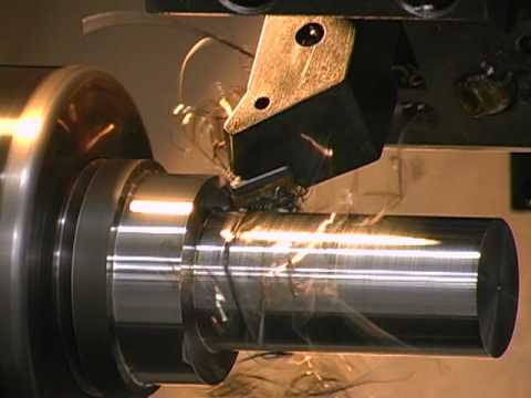
The main function of the cylinder body is to hold cylinder pressure. The cylinder barrel is mostly made from honed tubes. Honed tubes are produced from Suitable To Hone Steel Cold Drawn Seamless Tubes (CDS tubes) or Drawn Over Mandrel (DOM) tubes. Honed tubing is ready to use for hydraulic cylinders without further ID processing. The surface finish of the cylinder barrel is typically 4 to 16 microinch.Honing process and Skiving & Roller burnishing (SRB) process are the two main types of processes for manufacturing cylinder tube.The piston reciprocates in the cylinder.The cylinder barrel has features of smooth inside surface,high precision tolerance, durable in use etc.


Cylinder base or cap

The main function of the cap is to enclose the pressure chamber at one end. The cap is connected to the body by means of welding, threading, bolts, or tie rod. Caps also perform as cylinder mounting components [cap flange, cap trunnion, cap clevis]. Cap size is determined based on the bending stress. A static seal/o ring is used in between cap and barrel (except welded construction).


Cylinder head

The main function of the head is to enclose the pressure chamber from the other end. The head contains an integrated rod sealing arrangement or the option to accept a seal gland. The head is connected to the body by means of threading, bolts, or tie rod. A static seal/o ring  is used in between head and barrel.


Piston

The main function of the piston is to separate the pressure zones inside the barrel. The piston is machined with grooves to fit elastomeric  or metal seals and bearing elements. These seals can be single acting or double acting. The difference in pressure between the two sides of the piston causes the cylinder to extend and retract. The piston is attached with the piston rod by means of threads, bolts, or nuts to transfer the linear motion.


Piston rod

The piston rod is typically a hard chrome-plated piece of cold-rolled steel which attaches to the piston and extends from the cylinder through the rod-end head. In double rod-end cylinders, the actuator has a rod extending from both sides of the piston and out both ends of the barrel. The piston rod connects the hydraulic actuator to the machine component doing the work. This connection can be in the form of a machine thread or a mounting attachment. The piston rod is highly ground and polished so as to provide a reliable seal and prevent leakage.


Seal gland

The cylinder head is fitted with seals to prevent the pressurized oil from leaking past the interface between the rod and the head. This area is called the seal gland. The advantage of a seal gland is easy removal and seal replacement. The seal gland contains a primary seal, a secondary seal / buffer seal, bearing elements, wiper / scraper and static seal. In some cases, especially in small hydraulic cylinders, the rod gland and the bearing elements are made from a single integral machined part.


Seals


The seals are considered / designed as per the cylinder working pressure, cylinder speed, operating temparature , working medium and application. Piston seals are dynamic seals, and they can be single acting or double acting. Generally speaking, Elastomer seals made from nitrile rubber, Polyurethane or other materials are best in lower temperature environments, while seals made of Fluorocarbon  Viton are better for higher temperatures. Metallic seals are also available and commonly use cast iron for the seal material. Rod seals are dynamic seals and generally are single acting. The compounds of rod seals are nitrile rubber Polyurethane, or Fluorocarbon Viton . Wipers / scrapers are used to eliminate contaminants such as moisture, dirt, and dust, which can cause extensive damage to cylinder walls, rods, seals and other components. The common compound for wipers is polyurethane. Metallic scrapers are used for sub zero temperature applications, and applications where foreign materials can deposit on the rod. The bearing elements / wear bands are used to eliminate metal to metal contact. The wear bands are designed as per the side load requirements. The primary compounds used for wear bands are filled PTFE , woven fabric reinforced polyester resin and bronze


Other parts

There are many component parts that make up the internal portion of a hydraulic cylinder. All of these pieces combine to create a fully functioning component.


  • Cylinder base connection
  • Cushions
  • Internal Threaded Ductile Heads
  • Head Glands
  • Polypak Pistons
  • Cylinder Head Caps
  • Butt Plates
  • Eye Brackets/Clevis Brackets
  • MP Detachable Mounts
  • Rod Eyes/Rod Clevis
  • Pivot Pins
  • Spherical Ball Bushings
  • Spherical Rod Eye
  • Alignment Coupler
  • Ports and Fittings


Single acting vs. double acting


  • Single acting cylinders are economical and the simplest design. Hydraulic fluid enters through a port at one end of the cylinder, which extends the rod by means of area difference. An external force, internal retraction spring or gravity returns the piston rod.
  • Double acting cylinders have a port at each end or side of the piston, supplied with hydraulic fluid for both the retraction and extension.


Designs

There are primarily two main styles of hydraulic cylinder construction used in industry: tie rod style cylinders and welded body style cylinders.


Tie rod cylinder

A tie rod cylinder

Tie rod style hydraulic cylinders use high strength threaded steel rods to hold the two end caps to the cylinder barrel. They are most often seen in industrial factory applications. Small bore cylinders usually have 4 tie rods, and large bore cylinders may require as many as 16 or 20 tie rods in order to retain the end caps under the tremendous forces produced. Tie rod style cylinders can be completely disassembled for service and repair, and they are not always customizable.

The National fluid power assotation  (NFPA) has standardized the dimensions of hydraulic tie rod cylinders. This enables cylinders from different manufacturers to interchange within the same mountings.


Welded body cylinder

Welded body cylinders have no tie rods. The barrel is welded directly to the end caps. The ports are welded to the barrel. The front rod gland is usually threaded into or bolted to the cylinder barrel. That allows the piston rod assembly and the rod seals to be removed for service.A Cut Away of a Welded Body Hydraulic Cylinder showing the internal components

Welded body cylinders have a number of advantages over tie rod style cylinders. Welded cylinders have a narrower body and often a shorter overall length enabling them to fit better into the tight confines of machinery. Welded cylinders do not suffer from failure due to tie rod stretch at high pressures and long strokes. The welded design also lends itself to customization. Special features are easily added to the cylinder body, including special ports, custom mounts, valve manifolds, and so on.

The smooth outer body of welded cylinders also enables the design of multi-stage telescopic cylinders.

Welded body hydraulic cylinders dominate the mobile hydraulic equipment market such as construction equipment and material handling equipment (forklift trucks, telehandlers, and lift-gates). They are also used by heavy industry in cranes, oil rigs, and large off-road vehicles for above-ground mining operations.


Piston rod construction

The piston rod of a hydraulic cylinder operates both inside and outside the barrel, and consequently both in and out of the hydraulic fluid and surrounding atmosphere.


Coatings

Wear and corrosion resistant surfaces are desirable on the outer diameter of the piston rod. The surfaces are often applied using coating techniques such as Chrome (Nickel) Plating, Lunac 2+ duplex, Laser Cladding, PTA welding and Thermal Spraying. These coatings can be finished to the desirable surface roughness (Ra, Rz) where the seals give optimum performance. All these coating methods have their specific advantages and disadvantages. It is for this reason that coating experts play a crucial role in selecting the optimum surface treatment procedure for protecting Hydraulic Cylinders.

Cylinders are used in different operational conditions and that makes it a challenge to find the right coating solution. In dredging there might be impact from stones or other parts, in salt water environments there are extreme corrosion attacks, in off-shore cylinders facing bending and impact in combination with salt water, and in the steel industry there are high temperatures involved, etc. There is no single coating solution which successfully combats all the specific operational wear conditions. Every technique has its own benefits and disadvantages.


Length

Piston rods are generally available in lengths which are cut to suit the application. As the common rods have a soft or mild steel core, their ends can be welded or machined for a screw thread.


Distribution of forces on components

The forces on the piston face and the piston head retainer vary depending on which piston head retention system is used.

If a circlip (or any non preloaded system) is used, the force acting to separate the piston head and the cylinder shaft shoulder is the applied pressure multiplied by the area of the piston head. The piston head and shaft shoulder will separate and the load is fully reacted by the piston head retainer.

If a preloaded system is used the force between the cylinder shaft and piston head is initially the piston head retainer preload value. Once pressure is applied this force will reduce. The piston head and cylinder shaft shoulder will remain in contact unless the applied pressure multiplied by piston head area exceeds the preload.

The maximum force the piston head retainer will see is the larger of the preload and the applied pressure multiplied by the full piston head area. The load on the piston head retainer is greater than the external load, which is due to the reduced shaft size passing through the piston head. Increasing this portion of shaft reduces the load on the retainer.


Side loading

Side loading is unequal pressure that is not centered on the cylinder rod. This off-center strain can lead to bending of the rod in extreme cases, but more commonly causes leaking due to warping the circular seals into an oval shape. It can also damage and enlarge the bore hole around the rod and the inner cylinder wall around the piston head, if the rod is pressed hard enough sideways to fully compress and deform the seals to make metal-on-metal scraping contact.

The strain of side loading can be directly reduced with the use of internal stop tubes which reduce the maximum extension length, leaving some distance between the piston and bore seal, and increasing leverage to resist warping of the seals. Double pistons also spread out the forces of side loading while also reducing stroke length. Alternately, external sliding guides and hinges can support the load and reduce side loading forces applied directly on the cylinder.


Repair

Hydraulic cylinders form the heart of many hydraulic systems. It is a common practice to dissemble and rebuild an entire device in the case of hydraulic cylinder repair. Inspection of the leakage issue and scrutinizing cylinder parts (especially the seals) is helpful in recognizing the exact problem and choosing the repair options accordingly. Steps involved in the repair of hydraulic cylinders:


Disassembly

First of all, you should place the cylinder in a suitable location, which has sufficient space to work. If you are working in a cluttered space, it will be difficult for you to keep track of opened up parts. After bringing the cylinder to an appropriate spot, open the cylinder ports and drain out all the hydraulic fluid. The cover of cylinder can be removed by unscrewing the bolts. Once you take off the cover, remove the piston by loosening the input valves.


Diagnosis

Once the piston is completely removed, you will be able to see multiple seals on different parts that are connected to the piston rod . First of all, you need to examine the piston rod to see if there is any damage. If the shaft of the rod is bent or if the cylinder bore has scratches, then get them repaired at a professional repair shop. If the damage is permanent, then you can order or manufacture a new piston rod for your hydraulic cylinder. Piston seals can get damaged, be distorted, or worn. Such damaged seals can cause leakage of hydraulic fluid from the cylinder leading to lower overall pressure or inability to hold pressure. When such events occur, you know that these seals need to be replaced.


Repairing or replacing damaged parts

The parts of the hydraulic cylinder that are distorted (piston rod, rod seal, piston seal and/ or head of rod), need to be either repaired or completely replaced with new parts. The seals can be repacked with the help of a hydraulic cylinder seal kit. These kits will have seals and suitable o-rings. Remember the size and type of old seal while removing them and fix the new ones accordingly. Make sure that you handle the new seals with utmost care so that they do not get damaged in any way.


Rebuilding

Before reassembling all the parts of your cylinder, you should clean and dry the cylinder barrel completely. Also clean the piston rod, shaft, and other parts of the cylinder. Get the broken and damaged seals repacked. Then assemble the parts back on the piston rod. The assembly needs to be done in a reverse order. Once you have assembled all the parts back, put the rod into the soft-jaw vise and screw back the bolts onto the piston rod.


Important tip

If the parts of the hydraulic cylinder are severely damaged, then it is advisable to replace them with new parts with the help of a professional repair expert. Trying to replace/ repair too many parts on your own can lead to faulty reassembly. By following the above steps, you can accomplish the task of hydraulic cylinder repair. Make sure that you prevent ingress of moisture or dirt after assembly of the parts is done.


Cylinder mounting methods

Mounting methods also play an important role in cylinder performance. Generally, fixed mounts on the centerline of the cylinder are best for straight line force transfer and avoiding wear. Common types of mounting include:

Flange mounts—Very strong and rigid, but have little tolerance for misalignment. Experts recommend cap end mounts for thrust loads and rod end mounts where major loading puts the piston rod in tension. Three types are head rectangular flange, head square flange or rectangular head. Flange mounts function optimally when the mounting face attaches to a machine support member.

Side-mounted cylinders—Easy to install and service, but the mounts produce a turning moment as the cylinder applies force to a load, increasing wear and tear. To avoid this, specify a stroke at least as long as the bore size for side mount cylinders (heavy loading tends to make short stroke, large bore cylinders unstable). Side mounts need to be well aligned and the load supported and guided.

Centerline lug mounts —Absorb forces on the centerline, and require dowel pins to secure the lugs to prevent movement at higher pressures or under shock conditions. Dowel pins hold it to the machine when operating at high pressure or under shock loading.

Pivot mounts —Absorb force on the cylinder centerline and let the cylinder change alignment in one plane. Common types include clevises, trunnion mounts and spherical bearings. Because these mounts allow a cylinder to pivot, they should be used with rod-end attachments that also pivot. Clevis mounts can be used in any orientation and are generally recommended for short strokes and small- to medium-bore cylinders. 


Special hydraulic cylinders


Telescopic cylinder

The length of a hydraulic cylinder is the total of the stroke, the thickness of the piston, the thickness of bottom and head and the length of the connections. Often this length does not fit in the machine. In that case the piston rod is also used as a piston barrel and a second piston rod is used. These kinds of cylinders are called telescopic cylinder. If we call a normal rod cylinder single stage, telescopic cylinders are multi-stage units of two, three, four, five or more stages. In general telescopic cylinders are much more expensive than normal cylinders. Most telescopic cylinders are single acting (push). Double acting telescopic cylinders must be specially designed and manufactured.


Plunger cylinder

A hydraulic cylinder without a piston or with a piston without seals is called a plunger  cylinder. A plunger cylinder can only be used as a pushing cylinder; the maximum force is piston rod area multiplied by pressure. This means that a plunger cylinder in general has a relatively thick piston rod.


Differential cylinder

A differential cylinder acts like a normal cylinder when pulling. If the cylinder however has to push, the oil from the piston rod side of the cylinder is not returned to the reservoir, but goes to the bottom side of the cylinder. In such a way, the cylinder goes much faster, but the maximum force the cylinder can give is like a plunger cylinder. A differential cylinder can be manufactured like a normal cylinder, and only a special control is added.

The above differential cylinder is also called a regenerative cylinder control circuit. This term means that the cylinder is a single rod, double acting hydraulic cylinder. The control circuit includes a valve and piping which during the extension of the piston, conducts the oil from the rod side of the piston to the other side of the piston instead of to the pump’s reservoir. The oil which is conducted to the other side of the piston is referred to as the regenerative oil.


Position sensing “smart” hydraulic cylinder

Position sensing hydraulic cylinder  eliminate the need for a hollow cylinder rod. Instead, an external sensing “bar” using Hall effect  technology senses the position of the cylinder’s piston. This is accomplished by the placement of a permanent magnet within the piston. The magnet propagates a magnetic field through the steel wall of the cylinder, providing a locating signal to the sensor.


Terminology

In the United States, popular usage refers to the whole assembly of cylinder, piston, and piston rod (or more) collectively as a “piston”, which is incorrect. Instead, the piston is the short, cylindrical metal component that separates the two parts of the cylinder barrel internally.

You depend on hydraulic cylinders to help you deliver essential goods and services to your customers. Faulty cylinders translate into downtime. That’s lost money and time that you and those who depend on you can’t afford. When you need hydraulic cylinder repair, it makes sense to count on a company with a track record of high-quality repairs, reliable service and effective solutions. We delivers: dependable, rigorously-tested hydraulic repair, hydraulic pump repair and more that end downtime and return your production processes to peak efficiency.


  • Single or double end
  • Repair / replacement of rods, seals, piston heads, gland nuts, and tubes
  • Any diameter up to 14″ and lengths to 18′
  • Pressure testing after repair to 3,000 psi
  • Replacement seals rated up to 6,000 psi and 500 deg F

All hydraulic cylinders received for repair are disassembled, all components cleaned and inspected, rods are measured for straightness and wear. tubes are measured for wear and the seal / wear band grooves are measured and inspected.

All hydraulic cylinder repairs are dynamically tested to verify proper operation and leak free performance.


Expert Hydraulic Cylinder Repair

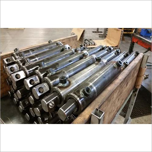
Cylinders are what is known as a “linear” actuator. Their basic operation is to move something in and out or up and down. The particular cylinder below is a “tie rod” type cylinders with “trunions” so that it can can pivot in it’s application. This cylinder is also an “oil or hydraulic” cylinder. The two basic cylinder configurations are “tie rod” and “mill” types. A tie rod cylinder has it’s end cap and seal gland cap held to the tube via tie rods. A mill cylinder has no end cap because it is a welded construction with the seal gland normally a screw in configuration. Cylinders can be used with oil, air, or water depending on their application and design. They also come in numerous shapes and sizes (bore and stroke) depending on their application.


You can find cylinders in virtually all industries. Another place to look in in the mobile industry. Large cylinders are used as shock absorbers on the large Quarry or Mining trucks, and on bulldozers, endloaders, etc. for various functions. They can also be found in the entertainment industry.


Accountability and Reliability

From the moment you contact K+S Services for hydraulic cylinder repair services, we dedicate our efforts to ensuring that you receive your parts back in exceptional working condition. The result is a cylinder that meets or exceeds OEM specifications and performs according to its original pressure rating. Our included Repair and Testing Report is complete with several key details for your review:


  • Problems identified
  • Parts repair or replaced
  • Testing details, duration and results
  • Probable root cause of failure
  • Recommended installation instructions

Some of the Hydraulic Cylinder and Servo Actuator brands we service and repair include: Anker-Holth, Boxtel-Holland, Caterpillar, Graco, Hanna, Hydroline, Instrom, Kress, Komatsu, Lynair, Miller Milwaukee, MTS, Moog, Nopak, Rexroth, Sheffer, Tomkins and more.Contact Us


Top 5 Hydraulic Cylinder Repair Tips

Hydraulic cylinders are an integral part of the hydraulic system. They are a mechanical actuator that provides the unidirectional force. Integration of hydraulic cylinders will eliminate the presence of levers and gears. Both mobile(hydraulic presses, cranes, forges, and packing machines) and industrial systems(agricultural machines, construction vehicles, marine equipment) utilize hydraulic systems. Among them, most of the application use hydraulic cylinders for lifting, picking and gripping. 

Every hydraulic system will contain basic components like pumps, cylinders, valves, filters, etc.. Hydraulic cylinder is one of the least complicated components in the list. So, they are easy to repair and maintain. A person having basic knowledge about the hydraulic system can perform hydraulic cylinder repairing. Before explaining the repairing of cylinders, I will give you brief details on the causes of hydraulic cylinder failure. Damage of seals is a common reason that creates hydraulic cylinder damage. Seal damage occurs as a result of the incorrect fitting, corrosion, inappropriate metalwork clearance, etc. Fluid contamination will damage the piston rod or seal surface. Improper alignment of cylinder and load will damage the rod bearings or piston rods. An internally corroded barrel will contaminate the fluid inside it. Extreme temperature and chemical attack are the other reasons for failure.

Before performing the repairing, clean the surface properly and disconnect the hoses and plugs attached to it. After disconnecting the parts, drain all the fluid present inside the cylinder. Now, let’s begin the repairing of the hydraulic system. For that we need tools. Proper seal kit, rubber mallet, screwdriver, punch, pliers, emery cloth, and torque wrench are the tools required for repairing. Leaking hydraulic cylinder is the most common issue that results in cylinder repair. Disassembly of the cylinder, diagnosing the cause of failure, repairing or replacing faulty components, and rebuilding the cylinder are the steps involved in cylinder repairing. During the process of hydraulic cylinder repairing, always consider the below-mentioned cylinder repair tips.


  1. If you disassemble the hydraulic cylinder as a part of repairing, inspect not only the failed part also perform a thorough inspection of all other components.
  2. Hydraulic wear bands(also called wear bush or guide ring) are used for guiding pistons. So, don’t forget to assemble the wear band because this will reduce the metal-to-metal contact. 
  3. Premature failure of rod seals indicates the bend on the rod. 
  4. Metal tools will scratch the surface of the cylinder and will create problems like corrosion. So always choose the best-fit tools for repairing.
  5. Larger hydraulic cylinders use high tension springs to perform operations. So, if you are an inexperienced worker, be careful while handling such cylinders.
  6. For replacing seals, don’t measure the existing size of the seal. It will expand or compress according to the environmental condition.

If you have any enquiries about hydraulic cylinder u can contact us at any time in a week we are reapiring cnc machines,Telescopic covers Repair ,Bellow covers Repair ,Appron cover Repair .Roll way cover Repair ,Hydarulic cylinders Repair ,Mechanical parts repair, Mavhine Spindle Repair , Ball screw Repair,Guideway Repair ,Lubrication Pump Repair ,Hydaulic cylinder Repair, CNC Machine Repair sevice ,VMC Machine Repair service,Preventive Maintenace service,HMC Machine repair service,Index table repair service,Rotary table repair service,Coolant pump repair service ,Counter balancing cylinder repair service,Panel ac repair service in Hoshiarpur,Jalandhar,Phagwara,Goraya,Ludhiana,Amritsar,Tarantaran,Patti,Batala,Gurdaspur,Pathankot,Jammu,Mukerian,Dasuya,Tanda,Gagret,Una,Baddi,Nangal,Tahliwal,Garhshankar,Anandpur sahib,Ropar,Nawansahar,Mandi gobindgarh, khanna,Moahli,Chandigarh,Nalagarh,Nasrala,Samarala,Rajpura,Patiala,Nabha,Malerkotla ,Bathinda,Moga,Firozpur and in all punjab and india.

Contact +91 7888776715,9915759967.


by soft_techkome soft_techkome No Comments

CNC Turning Machine

CNC Turning Machine

CNC Turning is a manufacturing process in which bars of material are held in a chuck and rotated while a tool is fed to the piece to remove material to create the desired shape. A turret , with tooling attached is programmed to move to the bar of raw material and remove material to create the programmed result. This is also called “subtraction machining” since it involves material removal. If the center has both tuning and milling capabilities, such as the one above, the rotation can be stopped to allow for milling out of other shapes.


  • The starting material, though usual round, can be other shapes such as squares or hexagons.
  • Depending on the bar feeder, the bar length can vary. This affects how much handling is required for volume jobs.
  • CNC lathes or turning centers have tooling mounted on a turret which is computer-controlled. The more tools that that the turret can hold, the more options are available for complexities on the part.
  • CNC’s with “live” tooling options, can stop the bar rotation and add additional features such as drilled holes, slots and milled surfaces.
  • Some CNC turning centers have one spindle, allowing work to be done all from one side, while other turning centers, such as the one shown above, have two spindles, a main and sub-spindle. A part can be partially machined on the main spindle, moved to the sub-spindle and have additional work done to the other side this configuration.
  • There are many different kinds of CNC turning centers with various types of tooling options, spindle options, outer diameter limitations as well as power and speed capabilities that affect the types of parts that can be economically made on it.

While a lot of factors go into determining if a part can be made most cost-effectively on a specific CNC turning center, some things we look at are:


  • How many parts are needed short-term and long-term?
  • What is the largest OD on the part ?
  • Price of machine
  • Easy avaliablity of machine

When it comes to machining parts, there are a lot of variables. Lot of Service providers can help you determine the best way to have your parts made.


We are dedicated, to provide, high quality products combined with excellent service. Thank you for your time and consideration. We hope you find the above in line with your requirement and eagerly look forward to serving you.

We are providing cnc repairing service  in .Amritsar,Batala, Chandigarh ,Jalandhar,Ludhiana ,Mandi Gobindgarh ,Mohali ,Patiala,Phagwara,Tarantaran ,Goraya,Hoshiarpur and in Punjab(India).

We are repairing CNC,VMC ,HMC spindle in punjab area 

Contact us +91 7888776715,9915759967

CNC turning machine


by soft_techkome soft_techkome No Comments

Conveyor

Conveyor system


conveyor system is a common piece of mechanical handling equipment that moves materials from one location to another. Conveyors are especially useful in applications involving the transportation of heavy or bulky materials. Conveyor systems allow quick and efficient transportation for a wide variety of materials, which make them very popular in the material handling and packing industries. They also have popular consumer applications, as they are often found in supermarkets and airports, constituting the final leg of item/ bag delivery to customers. Many kinds of conveying systems are available and are used according to the various needs of different industries. There are chain conveyors (floor and overhead) as well. Chain conveyors consist of enclosed tracks, I-Beam, towline, power & free, and hand pushed trolleys.


Industries that use conveyor systems

A line shaft roller conveyormoves boxed produce at a distribution center

A Conveyor conveys papers at a newspaper print plant

Roller conveyor for carton transport in the apparel industry

Conveyor systems are used widespread across a range of industries due to the numerous benefits they provide.


  • Conveyors are able to safely transport materials from one level to another, which when done by human labor would be strenuous and expensive.
  • They can be installed almost anywhere, and are much safer than using a forklift or other machine to move materials.
  • They can move loads of all shapes, sizes and weights. Also, many have advanced safety features that help prevent accidents.
  • There are a variety of options available for running conveying systems, including the hydraulic , mechanical and fully automated systems, which are equipped to fit individual needs.

Conveyor systems are commonly used in many industries, including the Mining, automotive, agriculture, computer , electronic, food proccesing , aerospace , pharmaceutical, chemical, bottling and canning, print finishing and packing. Although a wide variety of materials can be conveyed, some of the most common include food items such as beans and nuts, bottles and cans, automotive components, scrap metal, pills and powders, wood and furniture and grain and animal feed. Many factors are important in the accurate selection of a conveyor system. It is important to know how the conveyor system will be used beforehand. Some individual areas that are helpful to consider are the required conveyor operations, such as transportation, accumulation and sorting, the material sizes, weights and shapes and where the loading and pickup points need to be.


Care and maintenance of conveyor systems

A conveyor system is often the lifeline to a company’s ability to effectively move its product in a timely fashion. The steps that a company can take to ensure that it performs at peak capacity, include regular inspections and system audits, close monitoring of motors and reducers, keeping key parts in stock, and proper training of personnel.

Increasing the service life of a conveyor system involves: choosing the right conveyor type, the right system design and paying attention to regular maintenance practices.

A conveyor system that is designed properly will last a long time with proper maintenance. Here are six of the biggest problems to watch for in overhead type conveyor systems including I-beam monorails, enclosed track conveyors and power and free conveyors. Overhead conveyor systems have been used in numerous applications from shop displays, assembly lines to paint finishing plants and more.

Poor take-up adjustment: this is a simple adjustment on most systems yet it is often overlooked. The chain take-up device ensures that the chain is pulled tight as it leaves the drive unit. As wear occurs and the chain lengthens, the take-up extends under the force of its springs. As they extend, the spring force becomes less and the take-up has less effect. Simply compress the take-up springs and your problem goes away. Failure to do this can result in chain surging, jamming, and extreme wear on the track and chain. Take-up adjustment is also important for any conveyor using belts as a means to power rollers, or belts themselves being the mover. With poor-take up on belt-driven rollers, the belt may twist into the drive unit and cause damage, or at the least a noticeable decrease or complete loss of performance may occur. In the case of belt conveyors, a poor take-up may cause drive unit damage or may let the belt slip off of the side of the chassis.

Lack of lubrication: chain bearings require lubrication in order to reduce friction. The chain pull that the drive experiences can double if the bearings are not lubricated. This can cause the system to overload by either its mechanical or electrical overload protection. On conveyors that go through hot ovens, lubricators can be left on constantly or set to turn on every few cycles.

Contamination: paint, powder, acid or alkaline fluids, abrasives, glass bead, steel shot, etc. can all lead to rapid deterioration of track and chain. Ask any bearing company about the leading cause of bearing failure and they will point to contamination. Once a foreign substance lands on the raceway of a bearing or on the track, pitting of the surface will occur, and once the surface is compromised, wear will accelerate. Building shrouds around your conveyors can help prevent the ingress of contaminants. Or, pressurize the contained area using a simple fan and duct arrangement. Contamination can also apply to belts (causing slippage, or in the case of some materials premature wear), and of the motors themselves. Since the motors can generate a considerable amount of heat, keeping the surface clean is an almost-free maintenance procedure that can keep heat from getting trapped by dust and grime, which may lead to motor burnout.

Product handling: in conveyor systems that may be suited for a wide variety of products, such as those in distribution centers, it is important that each new product be deemed acceptable for conveying before being run through the materials handling equipment. Boxes that are too small, too large, too heavy, too light, or too awkwardly shaped may not convey, or may cause many problems including jams, excess wear on conveying equipment, motor overloads, belt breakage, or other damage, and may also consume extra man-hours in terms of picking up cases that slipped between rollers, or damaged product that was not meant for materials handling. If a product such as this manages to make it through most of the system, the sortation system will most likely be the affected, causing jams and failing to properly place items where they are assigned. Any and all cartons handled on any conveyor should be in good shape or spills, jams, downtime, and possible accidents and injuries may result.

Drive train: notwithstanding the above, involving take-up adjustment, other parts of the drive train should be kept in proper shape. Broken O-rings on a Lineshaft, pneumatic parts in disrepair, and motor reducers should also be inspected. Loss of power to even one or a few rollers on a conveyor can mean the difference between effective and timely delivery, and repetitive nuances that can continually cost downtime.

Bad belt tracking or timing: in a system that uses precisely controlled belts, such as a sorter system, regular inspections should be made that all belts are traveling at the proper speeds at all times. While usually a computer controls this with Pulse Position Indicators, any belt not controlled must be monitored to ensure accuracy and reduce the likelihood of problems. Timing is also important for any equipment that is instructed to precisely meter out items, such as a merge where one box pulls from all lines at one time. If one were to be mistimed, product would collide and disrupt operation. Timing is also important wherever a conveyor must “keep track” of where a box is, or improper operation will result.

Since a conveyor system is a critical link in a company’s ability to move its products in a timely fashion, any disruption of its operation can be costly. Most downtime can be avoided by taking steps to ensure a system operates at peak performance, including regular inspections, close monitoring of motors and reducers, keeping key parts in stock, and proper training of personnel.


Impact and wear-resistant materials used in conveyor systems

Conveyor systems require materials suited to the displacement of heavy loads and the wear-resistance to hold-up over time without seizing due to deformation. Where static control is a factor, special materials designed to either dissipate or conduct electrical charges are used. Examples of conveyor handling materials include UHMW, nylon, Nylatron NSM, HDPE, Tivar, Tivar ESd, and polyurethane.


Growth of conveyor systems in various industries

As far as growth is concerned the material handling and conveyor system makers are getting utmost exposure in the industries like automotive, pharmaceutical, packaging and different production plants. The portable conveyors are likewise growing fast in the construction sector and by the year 2014 the purchase rate for conveyor systems in North America, Europe and Asia is likely to grow even further. The most commonly purchased types of conveyors are line-shaft roller conveyors, chain conveyors and conveyor belts at packaging factories and industrial plants where usually product finishing and monitoring are carried. Commercial and civil sectors are increasingly implementing conveyors at airports, shopping malls, etc.


Types

Belt driven roller conveyor for cartons and totes.

Flexible conveyor


  • Aero-mechanical conveyor


  • Automotive conveyor


  • Belt conveyor


  • Belt-driven live roller conveyor


  • Bucket conveyor


  • Chain conveyor


  • Chain-driven live roller conveyor


  • Drag conveyor
  • Dust-proof conveyor
  • Electric track vehicle system
  • Flexible conveyor
  • Gravity conveyor
  • Gravity skatewheel conveyor
  • Line shaft roller conveyor
  • Motorized-drive roller conveyor
  • Over head I beam conveyor
  • Overland conveyor
  • Pharmaceutical conveyor
  • Plastic belt conver
  • Pneaumatic conveyor
  • screw or auger conveyor
  • Spiral conveyor
  • Vertical conveyor
  • Vibrating conveyor
  • Wire mesh conveyor


Pneumatic

Every pneumatic system uses pipes or ducts called transportation lines that carry a mixture of materials and a stream of air. These materials are free flowing powdery materials like cement and fly ash . Products are moved through tubes by air pressure. Pneumatic conveyors are either carrier systems or dilute-phase systems; carrier systems simply push items from one entry point to one exit point, such as the money-exchanging pneaumatic tubes used at a bank drive through window. Dilute-phase systems use push-pull pressure to guide materials through various entry and exit points. Air compressors or blowers can be used to generate the air flow. Three systems used to generate high-velocity air stream:


  1. Suction or vacuum systems, utilizing a vacuum created in the pipeline to draw the material with the surrounding air. The system operated at a low pressure, which is practically 0.4–0.5 atm below atmosphere, and is utilized mainly in conveying light free flowing materials.
  2. Pressure-type systems, in which a positive pressureis used to push material from one point to the next. The system is ideal for conveying material from one loading point to a number of unloading points. It operates at a pressure of 6 atm and upwards.
  3. Combination systems, in which a suction system is used to convey material from a number of loading points and a pressure system is employed to deliver it to a number of unloading points.


Vibrating

A vibrating conveyor is a machine with a solid conveying surface which is turned up on the side to form a trough. They are used extensively in food-grade applications to convey dry bulk solids  where sanitation, washdown, and low maintenance are essential. Vibrating conveyors are also suitable for harsh, very hot, dirty, or corrosive environments. They can be used to convey newly-cast metal parts which may reach upwards of 1,500 °F (820 °C). Due to the fixed nature of the conveying pans vibrating conveyors can also perform tasks such as sorting, screening, classifying and orienting parts. Vibrating conveyors have been built to convey material at angles exceeding 45° from horizontal using special pan shapes. Flat pans will convey most materials at a 5° incline from horizontal line.


Flexible

The flexible conveyor is based on a conveyor beam in aluminium or stainless steel , with low-friction slide rails guiding a plastic multi-flexing chain. Products to be conveyed travel directly on the conveyor, or on pallets/carriers. These conveyors can be worked around obstacles and keep production lines flowing. They are made at varying levels and can work in multiple environments. They are used in food packaging, case packing, and pharmaceutical industries and also in large retail stores such asWal mart  and K mart .


Spiral

Like Vertical conveyors , spiral conveyors raise and lower materials to different levels of a facility. In contrast, spiral conveyors are able to transport material loads in a continuous flow. A helical spiral or screw rotates within a sealed tube and the speed makes the product in the conveyor rotate with the screw. The tumbling effect provides a homogeneous mix of particles in the conveyor, which is essential when feeding pre-mixed ingredients and maintaining mixing integrity. Industries that require a higher output of materials – food and beverage, retail case packaging, pharmaceuticals – typically incorporate these conveyors into their systems over standard vertical conveyors due to their ability to facilitate high throughput. Most spiral conveyors also have a lower angle of incline or decline (11 degrees or less) to prevent sliding and tumbling during operation.


Vertical

Vertical conveyors, also commonly referred to as freight lifts and material lifts, are conveyor systems used to raise or lower materials to different levels of a facility during the handling process. Examples of these conveyors applied in the industrial assembly process include transporting materials to different floors. While similar in look to freight elevators, vertical conveyors are not equipped to transport people, only materials.

Vertical lift conveyors contain two adjacent, parallel conveyors for simultaneous upward movement of adjacent surfaces of the parallel conveyors. One of the conveyors normally has spaced apart flights (pans) for transporting bulk food items. The dual conveyors rotate in opposite directions, but are operated from one gear box to ensure equal belt speed. One of the conveyors is pivotally hinged to the other conveyor for swinging the attached conveyor away from the remaining conveyor for access to the facing surfaces of the parallel conveyors.[3] Vertical lift conveyors can be manually or automatically loaded and controlled.[4] Almost all vertical conveyors can be systematically integrated with horizontal conveyors, since both of these conveyor systems work in tandem to create a cohesive material handling assembly line.

Like Spiral conveyors , vertical conveyors that use forks can transport material loads in a continuous flow. With these forks the load can be taken from one horizontal conveyor and put down on another horizontal conveyor on a different level. By adding more forks, more products can be lifted at the same time. Conventional vertical conveyors must have input and output of material loads moving in the same direction. By using forks many combinations of different input- and output- levels in different directions are possible. A vertical conveyor with forks can even be used as a vertical sorter. Compared to a spiral conveyor a vertical conveyor – with or without forks – takes up less space.

Vertical reciprocating conveyors are another type of unit handling system. Typical applications include moving unit loads between floor levels, working with multiple accumulation conveyors, and interfacing overhead conveyors line. Common material to be conveyed includes pallets, sacks, custom fixtures or product racks and more.


Heavy-duty roller

Heavy-duty roller conveyors are used for moving items that weigh at least 500 pounds (230 kg). This type of conveyor makes the handling of such heavy equipment/products easier and more time effective. Many of the heavy duty roller conveyors can move as fast as 75 feet per minute (23 m/min).

Other types of heavy-duty roller conveyors are gravity roller conveyors, chain-driven live roller conveyors, pallet accumulation conveyors, multi-strand chain conveyors, and chain and roller transfers.

Gravity roller conveyors are easy to use and are used in many different types of industries such as automotive and retail.

Chain-driven live roller conveyors are used for single or bi-directional material handling. Large, heavy loads are moved by chain driven live roller conveyors.

Pallet accumulation conveyors are powered through a mechanical clutch. This is used instead of individually powered and controlled sections of conveyors.

Multi-strand chain conveyors are used for double-pitch roller chains. Products that cannot be moved on traditional roller conveyors can be moved by a multi-strand chain conveyor.

Chain and roller conveyors are short runs of two or more strands of double-pitch chain conveyors built into a chain-driven line roller conveyor. These pop up under the load and move the load off of the conveyor.


by soft_techkome soft_techkome No Comments

Speeds and feeds

A line drawing showing some basic concepts of speeds and feeds in the context of lathe work. The angular velocity of the workpiece (rev/min) is called the “spindle speed” by machinists. Its tangential linear equivalent at the workpiece surface is called the “cutting speed”, “surface speed”, or simply the “speed” by machinists. The “feeds” may be for the X-axis or the Z-axis (typically mm/rev or inch/rev for lathe work; sometimes measured as mm/min or inch/min). Notice that as the tool plunges closer to the workpiece’s center, the same spindle speed will yield a decreasing surface (cutting) speed (because each rev represents a smaller circumfrance distance, but takes the same amount of time). Most cnc lathes have constant surface feed to counteract that natural decrease, which speeds up the spindle as the tool plunges in.

Milling cutter paused after taking a cut. Arrows show the vectors of various velocities collectively known as speeds and feeds. The circular arrow represents the angular velocity of the spindle (rev/min), called the “spindle speed” by machinists. The tangential arrow represents the tangential linear velocity at the outer diameter of the cutter, called the “cutting speed”, “surface speed”, or simply the “speed” by machinists. The arrow colinear with the slot that has been milled represents the linear velocity at which the cutter is advanced laterally . This velocity is called the “feed” by machinists.

The phrase speeds and feeds or feeds and speeds refers to two separate velocities in machine tool practice, cutting speed and feed rate. They are often considered as a pair because of their combined effect on the cutting process. Each, however, can also be considered and analyzed in its own right.

Cutting speed  is the speed difference between the cutting tool and the surface of the workpiece it is operating on. It is expressed in units of distance across the workpiece surface per unit of time, typically surface feey per minute  or meters  per minute   Feed rate is the relative velocity at which the cutter is advanced along the workpiece; its vector is perpendicular  to the vector of cutting speed. Feed rate units depend on the motion of the tool and workpiece; when the workpiece rotates , the units are almost always distance per spindle revolution (inches per revolution [in/rev or ipr] or millimeters per revolution . When the workpiece does not rotate , the units are typically distance per time (inches per minute or millimeters per minute , although distance per revolution or per cutter tooth are also sometimes used.

Cutting speed

Cutting speed may be defined as the rate at the workpiece surface, irrespective of the machining operation used. A cutting speed for mild steel of 100 ft/min is the same whether it is the speed of the cutter passing over the workpiece, such as in a turning operation, or the speed of the cutter moving past a workpiece, such as in a milling operation. The cutting conditions will affect the value of this surface speed for mild steel.

Schematically, speed at the workpiece surface can be thought of as the tangetial  speed at the tool-cutter interface, that is, how fast the material moves past the cutting edge of the tool, although “which surface to focus on” is a topic with several valid answers. In drilling and milling, the outside diameter of the tool is the widely agreed surface. In turning and boring, the surface can be defined on either side of the depth of cut, that is, either the starting surface or the ending surface, with neither definition being “wrong” as long as the people involved understand the difference. An experienced machinist summed this up succinctly as “the diameter I am turning from” versus “the diameter I am turning to.” He uses the “from”, not the “to”, and explains why, while acknowledging that some others do not. The logic of focusing on the largest diameter involved (OD of drill or end mill, starting diameter of turned workpiece) is that this is where the highest tangential speed is, with the most heat generation, which is the main driver of tool wear

There will be an optimum cutting speed for each material and set of machining conditions, and the spindle speed can be calculated from this speed. Factors affecting the calculation of cutting speed are:

  • The material being machined (steel, brass, tool steel, plastic, wood) (see table below)
  • The material the cutter is made from High carbon steel ,hisg speed steel, Carbide, Ceramic , and Diamond tools
  • The economical life of the cutter (the cost to regrind or purchase new, compared to the quantity of parts produced)

Cutting speeds are calculated on the assumption that optimum cutting conditions exist. These include:

  • Metal removal rate
  • Full and constant flow of cutting fluid  
  • Rigidity of the machine and tooling setup
  • Continuity of cut
  • Condition of material

The cutting speed is given as a set of constants that are available from the material manufacturer or supplier. The most common materials are available in reference books or charts, but will always be subject to adjustment depending on the cutting conditions. The following table gives the cutting speeds for a selection of common materials under one set of conditions. The conditions are a tool life of 1 hour, dry cutting (no coolant), and at medium feeds, so they may appear to be incorrect depending on circumstances. These cutting speeds may change if, for instance, adequate coolant is available or an improved grade of HSS is used (such as one that includes [cobalt]).

Spindle speed

The spindle speed is the rotational frequency of the spindle of the machine, measured in revolutions per minute (RPM). The preferred speed is determined by working backward from the desired surface speed (sfm or m/min) and incorporating the diameter (of workpiece or cutter).

Excessive spindle speed will cause premature tool wear, breakages, and can cause tool chatter, all of which can lead to potentially dangerous conditions. Using the correct spindle speed for the material and tools will greatly enhance tool life and the quality of the surface finish.

Grinding wheels are designed to be run at a maximum safe speed, the spindle speed of the grinding machine may be variable but this should only be changed with due attention to the safe working speed of the wheel. As a wheel wears it will decrease in diameter, and its effective cutting speed will be reduced. Some grinders have the provision to increase the spindle speed, which corrects for this loss of cutting ability; however, increasing the speed beyond the wheels rating will destroy the wheel and create a serious hazard to life and limb.

Spindle speed becomes important in the operation of routers, spindle moulders or shapers, and drills. Older and smaller routers often rotate at a fixed spindle speed, usually between 20,000 and 25,000 rpm. While these speeds are fine for small router bits, using larger bits, say more than 1-inch (25 mm) or 25 millimeters in diameter, can be dangerous and can lead to chatter. Larger routers now have variable speeds and larger bits require slower speed. drilling goods  generally uses higher spindle speeds than metal, and the speed is not as critical. However, larger diameter drill bits do require slower speeds to avoid burning.

Cutting feeds and speeds, and the spindle speeds that are derived from them, are the ideal cutting conditions for a tool. If the conditions are less than ideal then adjustments are made to the spindle’s speed, this adjustment is usually a reduction in RPM to the closest available speed, or one that is deemed to be correct.

Spindle speed calculations

Most metalworking books have nomograms or tables of spindle speeds and feed rates for different cutters and workpiece materials; similar tables are also likely available from the manufacturer of the cutter used.

The spindle speeds may be calculated for all machining operations once the SFM or MPM is known. In most cases, we are dealing with a cylindrical object such as a milling cutter or a workpiece turning in a lathe so we need to determine the speed at the periphery of this round object. This speed at the periphery (of a point on the circumference, moving past a stationary point) will depend on the rotational speed (RPM) and diameter of the object.

The following formulae may be used to estimate this value.

Approximation

 {\pi }

The exact RPM is not always needed, a close approximation will work (using 3 for the value of {\displaystyle {\pi }}).{\displaystyle RPM={CuttingSpeed\times 12 \over \pi \times Diameter}}

RPM = {Cutting Speed\times 12 \over \pi \times Diameter}

e.g. for a cutting speed of 100 ft/min (a plain HSS steel cutter on mild steel) and diameter of 10 inches (the cutter or the work piece){\displaystyle RPM={CuttingSpeed\times 12 \over \pi \times Diameter}={12\times 100ft/min \over 3\times 10inches}={40revs/min}}

RPM = {Cutting Speed\times 12 \over \pi \times Diameter} = {12 \times 100 ft/min \over 3 \times 10 inches} = {40 revs/min}

and, for an example using metric values, where the cutting speed is 30 m/min and a diameter of 10 mm (0.01 m),{\displaystyle RPM={Speed \over \pi \times Diameter}={1000\times 30m/min \over 3\times 10mm}={1000revs/min}}

{\displaystyle RPM={Speed \over \pi \times Diameter}={1000\times 30m/min \over 3\times 10mm}={1000revs/min}}

Accuracy

However, for more accurate calculations, and at the expense of simplicity, this formula can be used:{\displaystyle RPM={Speed \over Circumference}={Speed \over \pi \times Diameter}}

RPM = {Speed \over Circumference}={Speed \over \pi \times Diameter}

and using the same example{\displaystyle RPM={100ft/min \over \pi \times 10\,inches\left({\frac {1ft}{12\,inches}}\right)}={100 \over 2.62}=38.2revs/min}

RPM = {100 ft/min \over \pi \times 10 \, inches \left ( \frac{1 ft}{12 \, inches} \right )} = {100 \over 2.62} = 38.2 revs/min

and using the same example as above{\displaystyle RPM={30m/min \over \pi \times 10\,mm\left({\frac {1m}{1000\,mm}}\right)}={1000*30 \over \pi *10}=955revs/min}

RPM = {30 m/min \over \pi \times 10 \, mm \left ( \frac{1 m}{1000 \, mm} \right )} = {1000*30 \over \pi*10} = 955 revs/min

where:

  • RPM is the rotational speed of the cutter or workpiece.
  • Speed is the recommended cutting speed of the material in meters/minute or feet/min
  • Diameter in millimeters or inches.

Feed rate

Feed rate is the velocity at which the cutter is fed, that is, advanced against the workpiece. It is expressed in units of distance per revolution for turning and boring (typically inches per revolution [ipr] or millimeters per revolution). It can be expressed thus for milling also, but it is often expressed in units of distance per time for milling (typically inches per minute [ipm] or millimeters per minute), with considerations of how many teeth (or flutes) the cutter has then determined what that means for each tooth.

Feed rate is dependent on the:

  • Type of tool (a small drill or a large drill, high speed or carbide, a boxtool or recess, a thin form tool or wide form tool, a slide knurl or a turret straddle knurl).
  • Surface finish desired.
  • Power available at the spindle
  • Rigidity of the machine and tooling setup
  • Strength of the workpiece
  • Characteristics of the material being cut, chip flow depends on material type and feed rate. The ideal chip shape is small and breaks free early, carrying heat away from the tool and work.
  • Threads per inch  (TPI) for taps, die heads and threading tools.
  • Cut Width. Any time the width of cut is less than half the diameter, a geometric phenomenon called Chip Thinning reduces the actual chipload. Feedrates need to be increased to offset the effects of chip thinning, both for productivity and to avoid rubbing which reduces tool life.

When deciding what feed rate to use for a certain cutting operation, the calculation is fairly straightforward for single-point cutting tools, because all of the cutting work is done at one poi. With a milling machine or jointer, where multi-tipped/multi-fluted cutting tools are involved, then the desired feed rate becomes dependent on the number of teeth on the cutter, as well as the desired amount of material per tooth to cut .The greater the number of cutting edges, the higher the feed rate permissible: for a cutting edge to work efficiently it must remove sufficient material to cut rather than rub; it also must do its fair share of work.

Formula to determine feed rate

This formula can be used to figure out the feed rate that the cutter travels into or around the work. This would apply to cutters on a milling machine, drill press and a number of other machine tools. This is not to be used on the lathe for turning operations, as the feed rate on a lathe is given as feed per revolution.

FR = {RPM \times T \times CL}

{\displaystyle FR={RPM\times T\times CL}}

Where:

  • FR = the calculated feed rate in inches per minute or mm per minute.
  • RPM = is the calculated speed for the cutter.
  • T = Number of teeth on the cutter.
  • CL = The chip load or feed per tooth. This is the size of chip that each tooth of the cutter takes.

Depth of cut

Cutting speed and feed rate come together with depth of cut to determine the material removal rate , which is the volume of workpiece material (metal, wood, plastic, etc.) that can be removed per time unit.

We are dedicated, to provide, high quality products combined with excellent service. Thank you for your time and consideration. We hope you find the above in line with your requirement and eagerly look forward to serving you.

We are providing cnc repairing service  in .Amritsar,Batala, Chandigarh ,Jalandhar,Ludhiana ,Mandi Gobindgarh ,Mohali ,Patiala,Phagwara,Tarantaran ,Goraya,Hoshiarpur and in Punjab(India).

We are repairing CNC,VMC ,HMC spindle in punjab area .

Contacts; +91 7888776715,9915759967.

by soft_techkome soft_techkome No Comments

Spindle

In machine tool, a spindlehttp://https://www.youtube.com/watch?v=7Qah4iledMQ is a Rotating axis of the machine, which often has a Shaft at its heart. The shaft itself is called a spindle, but also, in shop-floor practice, the word often is used metonymically to refer to the entire rotary unit, including not only the shaft itself, but its bearings and anything attached to it

A machine tool may have several , such as the headstock and tailstock on a bench lathe. That is usually the biggest one. References to “the spindle” without further qualification imply the main . Some machine tools that specialize in high-volume mass production have a group of 4, 6, or even more main .


Contents 

High speed spindle

High speed spindles are used strictly in machines, like CNC mills designed for metal work. There are two types of high speed , each with different designs:


Belt-driven spindle

Consisting of spindle and bearing shafts held within the spindle housing, the belt-driven spindle is powered by an external motor connected via a belt-pulley system.


Integral motor spindle


  • Internal Motor: limited power and torque due to restricted space within the  housing
  • Speed Range: 20,000-60,000 RPM
  • Advantage: high top speed expands application use
  • Disadvantage: sensitive life range according to use

Both types, the belt-driven and the integral motor , have advantages and disadvantages according to their design. Which one is more desirable depends on the purpose of the machine and product(s) being produced.

We are pleased to introduce ourselves, as one of the leading CNC machine repairing service provider at India, Service providing to customer for  reconditioning & repairing  in at Phagwara,Hoshiarpur ,Jalandhar,Amritsar,Batala and Ludhiana. we are also providing services at Chandigarh and near cities  Mohali , Panchkula ,Nalagarh and Baddi .We have some customer at  Ambala and surronding at  Harayana region. We are also providing cnc repairing servive at goraya near Phagwara very well.We are providing  VMC repair service in at  jalandhar and HMC  repair servive in at jalandhar. we are providing perfectcncsolution  and  top in machine tool  repair service provider in Ludhiana and  punjab.


For any machine repair related queary contact +91 7888776715,9915759967.

 Spindle